I will one dayBas - you should reconsider and complete the project.
")
PS. Great job you did!
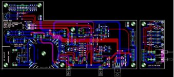
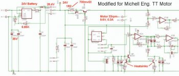
Hi MarK. Thanks for your help and usefull comments. Here most of the modifications that you suggested on your original schematic to make it work with my own motor. I modified the battery charger to accept the new 24V battery and change R4 to 1R2 (exact value still to confirm)
I'm on the road and I will need to validate the exact motor current when I'll be back. In the mean time, Mark can you validate my calculations for the L200C battery charger modified for the 24V battery?
L200C
Vout = Vref (1+R2/R1) where Vref = 2.770V
Io = Vpin5-Vpin2 / R3
Ver1.0 set for 12V Battery
values where R1=750R, R2=3K, R3=0.75
For 24V Battery
Typical float voltage (lead-acid) is 2.15 to 2.23V per cell, or 12.9 to 13.4V for a 12V Battery. So for a 24V battery, float voltage = 2.20 * 12 = 26.4V + 0.7V (D1 diode) = 27.1V
R2 = ((27.1V/2.770V) - 1) * 750R = 6587R (closest value 6.65K) = 27.3V
Q2 & Q8 are already mounted on a very good heatsink. I'll install small TO92 heatsinks on Q3 & Q4.
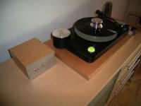
On my circuit, I will also to change the charger transformer and use an external 24V battery. My design already included the option to use an external battery, so I'm convered. My current transformer is a TE70033, 15V, 04A (parallel secondaries), or 30V, 0.233A (sec in serie). I'll keep the same transformer, but just modify the PCB to connect both secondaries in serie.
I guest I will also need to modify the LED's indicator Zener to accept the new 24V working voltage
I'm on the road and I will need to validate the exact motor current when I'll be back. In the mean time, Mark can you validate my calculations for the L200C battery charger modified for the 24V battery?
L200C
Vout = Vref (1+R2/R1) where Vref = 2.770V
Io = Vpin5-Vpin2 / R3
Ver1.0 set for 12V Battery
values where R1=750R, R2=3K, R3=0.75
For 24V Battery
Typical float voltage (lead-acid) is 2.15 to 2.23V per cell, or 12.9 to 13.4V for a 12V Battery. So for a 24V battery, float voltage = 2.20 * 12 = 26.4V + 0.7V (D1 diode) = 27.1V
R2 = ((27.1V/2.770V) - 1) * 750R = 6587R (closest value 6.65K) = 27.3V
Q2 & Q8 are already mounted on a very good heatsink. I'll install small TO92 heatsinks on Q3 & Q4.
On my circuit, I will also to change the charger transformer and use an external 24V battery. My design already included the option to use an external battery, so I'm convered. My current transformer is a TE70033, 15V, 04A (parallel secondaries), or 30V, 0.233A (sec in serie). I'll keep the same transformer, but just modify the PCB to connect both secondaries in serie.
I guest I will also need to modify the LED's indicator Zener to accept the new 24V working voltage
Attachments
Re: OPA2777 Supply running at 24V
Yes, because the opamp sits between the rails so at +24V / ground it is seeing +/- 12 on its rails (the opamp voltage spec allows for swinging to rails).
BTW I assume 2777 is a typo.
Algar_emi said:Hi Mark. One problem may be to use the OPA2777 with the new 24V supply voltage. This op-amp is specified for a maximum of +/-18V supply range. Will it work with a supply of 0V and 24V?
Yes, because the opamp sits between the rails so at +24V / ground it is seeing +/- 12 on its rails (the opamp voltage spec allows for swinging to rails).
BTW I assume 2777 is a typo.
Re: Re: OPA2777 Supply running at 24V
Hi Mike,
Just a new guy entering the block, do you still sell PCB's for the motor controller? if so is it possible to sell me one?
please mail me to rui.lourenco@fortislease.com
thanks
Hi Mike,
Just a new guy entering the block, do you still sell PCB's for the motor controller? if so is it possible to sell me one?
please mail me to rui.lourenco@fortislease.com
thanks
Hello Mr.Kelly,
one more late post. Maybe you still have the pcb's?
Please contact me on :
mcotar@hotmail.com
Thank you a lot
best regards,
Boris
one more late post. Maybe you still have the pcb's?
Please contact me on :
mcotar@hotmail.com
Thank you a lot
best regards,
Boris
Also if I cannot get any motor, I would like to start a new group buy for 5 motors minimum. I can supply my own version of Mark Kelly PCB also if you need it. I'm waiting to see if there is any interest. Please email me.
By the way Mark Kelly just posted his PCB, so I can make his PCB too if you prefer...
By the way Mark Kelly just posted his PCB, so I can make his PCB too if you prefer...
Wake up Gentlemen........
If you guys want motors, pulleys and Mark Kelly Motor Controller PCB's you better get your butts in gear and go to the new group buy thread and sign up quickly. There is only two weeks left and posting your wants in this thread won't get it done for you.
Post what you want in this thread:
http://www.diyaudio.com/forums/showthread.php?s=&threadid=109934&perpage=25&pagenumber=1
- Status
- This old topic is closed. If you want to reopen this topic, contact a moderator using the "Report Post" button.
- Home
- Group Buys
- Who is interested in a groupbuy of Mark Kelly's DC controller PCB and related parts