Voltage readings
I understood from your last post that you were having trouble getting the controller to hold a steady output voltage. If that is the case then a quick check of the output voltages of the various active devices would help me find the problem. If it isn't the case there's no need.
I understood from your last post that you were having trouble getting the controller to hold a steady output voltage. If that is the case then a quick check of the output voltages of the various active devices would help me find the problem. If it isn't the case there's no need.
An externally hosted image should be here but it was not working when we last tested it.
Up and running ! Enclosure time...
Sorry guys but mine doesn't work. It worked for a week than the speed started to flow and suddenly stopped definitly.
REF02 was substituted because the Vout was less than 1V. I installed a new battery and charged it , it worked for few hours but now the platter doesn't start to turn by its own , I have to help him but it never catch up the right speed, its too slow. I hope you can help me because I lost too many hours without getting out of this trouble.
I have those voltages with dip switch settled for 45rpm as Mark xls file:
Vx2-3= 13,8V
Vcc=12,7V
Vmotor 6,15V with motor disconnected, with motor connected 3,45V
all following tension are with motor disconnected
IC3 Vout 4,99 with JP2 in the outer position(motor negative) and 10,22V to ground
Q2 base 11,1V, Vc.11,4, Ve11,9V
The turntable platter weight is about 6kg. can be this a problem in the start up?
Giorgio
Q3 Vc 5,27 Vb 0,12 Ve 0,00
Q4 Vc 8,32 Vb 0,12 Ve 0,00
Q5 Vc 12,7 Vb 5,2 Ve 0,12
Q6 Vc 0,68 Vb 10,8 Ve 11,4
Q7 Vb 10,26 Ve 10,8
Q8 Vc 11,4 Vb 0,68
IC3 Vout 4,99 referring to negative supply motor and 10,2 to ground
IC2 pin1 8,3 pin3 8,2 pin5 8,3 pin7 8,3
IC4 pin1 10,2 pin2 8,3 pin5 8,3 pin7 8,3
The platter weight is about 6kg. could be this a problem in the start up for this power supply?
Regards
Giorgio
Re: less is more...
Thanks, I haven't really put much work ( or thought ) into what you see on that picture, the 80mm acrylic platter is from shceu, so is the bearing, ( inverted, ceramic ball ) I got it second hand from someone in Norway who had hardly used it.
http://www.highend-sound.com/produkter/detail.asp?iType=24&iAd=92
I put the motor in a piece of 100mmx100m alu-pipe and considerd "cramming" the controlller in there to, but i figured it would be a problem getting enough damping. There is vibration noise.
The plinth is simply 15mm clear acrylic. I am considering all kinds of alternativs, wallmounting is no option , so vibration damping will be an issue here also.
Reading all the Norwegian comments can be a challange, but this thread also features some of my design ideas:
http://www.hifisentralen.no/cgi/yabb/YaBB.cgi/YaBB.cgi?board=hifi2;action=display;num=1176420883
sklimek said:
Hi superhkm, your turntable is absolutely beautiful! Would you care to talk about it, materials, sources, execution?
Best - Stan
Thanks, I haven't really put much work ( or thought ) into what you see on that picture, the 80mm acrylic platter is from shceu, so is the bearing, ( inverted, ceramic ball ) I got it second hand from someone in Norway who had hardly used it.
http://www.highend-sound.com/produkter/detail.asp?iType=24&iAd=92
I put the motor in a piece of 100mmx100m alu-pipe and considerd "cramming" the controlller in there to, but i figured it would be a problem getting enough damping. There is vibration noise.
The plinth is simply 15mm clear acrylic. I am considering all kinds of alternativs, wallmounting is no option , so vibration damping will be an issue here also.
Reading all the Norwegian comments can be a challange, but this thread also features some of my design ideas:
http://www.hifisentralen.no/cgi/yabb/YaBB.cgi/YaBB.cgi?board=hifi2;action=display;num=1176420883
patriz said:Sorry guys but mine doesn't work.
Vmotor 6,15V with motor disconnected, with motor connected 3,45V
Giorgio
The current compensation part of the circuit would appear to be the likely fault, as the voltage at the motor should increase when loaded (the supply has a negative output impedance).
Check the small transistors Q3, Q4 and Q5 in the current compensation circuit.
Measure the voltage at each of the three with no load on the drive. Connect a resistance of 100 ohms as a load and check them again. Post the results.
Re: Ping Mark Kelly
Not yet. It's become a little more complex, I decided to use a high end AD Direct Digital Synthesis chip as the primary frequency source and I lack the software skills to write the prgramming needed for the micro which controls the DDS. Jose Korneluk is writing the software.
On another note I seem to have found a way to eliminate cogging so I'm chasing that as well, again slowing the development down. Wish me luck
Tonyb said:Hi Mark,
Could you, please, drop me a line about your 3 phase turntable Maxon motor? Is it still available?
TonyB
Not yet. It's become a little more complex, I decided to use a high end AD Direct Digital Synthesis chip as the primary frequency source and I lack the software skills to write the prgramming needed for the micro which controls the DDS. Jose Korneluk is writing the software.
On another note I seem to have found a way to eliminate cogging so I'm chasing that as well, again slowing the development down. Wish me luck
Re: Re: Ping Mark Kelly
Hi Mark,
I planned to do it very similarly - either a DDS chip or synthesize it directly by a uP since the frequency is quite low. I thought that you wanted to sell the Maxon 3 phase motor. That is why I wrote the previous post.
Does a 3 phave AC motor cog? If yes, I would be interested what you do to eliminate cogging.
Regards,
TonyB
Hi Mark,
Mark Kelly said:
Not yet. It's become a little more complex, I decided to use a high end AD Direct Digital Synthesis chip as the primary frequency source and I lack the software skills to write the prgramming needed for the micro which controls the DDS. Jose Korneluk is writing the software.
On another note I seem to have found a way to eliminate cogging so I'm chasing that as well, again slowing the development down. Wish me luck
I planned to do it very similarly - either a DDS chip or synthesize it directly by a uP since the frequency is quite low. I thought that you wanted to sell the Maxon 3 phase motor. That is why I wrote the previous post.
Does a 3 phave AC motor cog? If yes, I would be interested what you do to eliminate cogging.
Regards,
TonyB
Mark Kelly said:
The current compensation part of the circuit would appear to be the likely fault, as the voltage at the motor should increase when loaded (the supply has a negative output impedance).
Check the small transistors Q3, Q4 and Q5 in the current compensation circuit.
Measure the voltage at each of the three with no load on the drive. Connect a resistance of 100 ohms as a load and check them again. Post the results.
Hi Mark
I installed the 100R resistor and those are the measurements:
Vmotor 1,48
IC3 Vo 1,33 referred to neg motor and 11,55 to ground
Q5 Vc 12,7 Vb 10,0 Ve 0,31
Q4 Vc10,93 Vb 0,30 Ve 0,00
Q3 Vc 10,09 Vb 0,30 Ve0,00
As you can see IC3 Vout has dropped from 4,99 to 1,33 , previously I thought was REF02 defective and I substituted it but now is the same, do you think I have to replace Q3,Q4,Q5?
Giorgio
patriz said:
Vmotor 1,48
IC3 Vo 1,33 referred to neg motor and 11,55 to ground
Q5 Vc 12,7 Vb 10,0 Ve 0,31
Q4 Vc10,93 Vb 0,30 Ve 0,00
Q3 Vc 10,09 Vb 0,30 Ve0,00
do you think I have to replace Q3,Q4,Q5?
Giorgio
Yes definitely. I think Q3 is dead, I would expect to see about 1.2 volts at its collector when healthy.
Re: Re: Re: Ping Mark Kelly
Yes, they cog because they must be run at a voltage higher than the back EMF in order to drive current across the windings. This current doesn't follow the sine squared law so the phase combination doesn't sum to zero, the residual causes cogging. The cogging is less severe than in an ordinary (two phase) synch motor but it's still there.
The usual solution is to run the motor as BLDC, using voltage control of speed and sensor feedback to synchronise the frequency. My circuit is different but still experimental, if it works it will also apply to ordinary synch motors as well.
It has changed my mind about the possibilities for the Maxon so I'm not selling. I am planning to try one of Thingap's motors as well.
Tonyb said:
I thought that you wanted to sell the Maxon 3 phase motor. That is why I wrote the previous post.
Does a 3 phave AC motor cog? If yes, I would be interested what you do to eliminate cogging.
TonyB
Yes, they cog because they must be run at a voltage higher than the back EMF in order to drive current across the windings. This current doesn't follow the sine squared law so the phase combination doesn't sum to zero, the residual causes cogging. The cogging is less severe than in an ordinary (two phase) synch motor but it's still there.
The usual solution is to run the motor as BLDC, using voltage control of speed and sensor feedback to synchronise the frequency. My circuit is different but still experimental, if it works it will also apply to ordinary synch motors as well.
It has changed my mind about the possibilities for the Maxon so I'm not selling. I am planning to try one of Thingap's motors as well.
Re: Re: Re: Re: Ping Mark Kelly
Hi Mark,
I also thought of other approaches. Use of current sources was one of the thoughts.
Funny, through a different route I also came to ThinGap motors with their "zero" torque jitter.
Regards,
TonyB
Hi Mark,
Mark Kelly said:
My circuit is different but still experimental, if it works it will also apply to ordinary synch motors as well.
It has changed my mind about the possibilities for the Maxon so I'm not selling. I am planning to try one of Thingap's motors as well.
I also thought of other approaches. Use of current sources was one of the thoughts.
Funny, through a different route I also came to ThinGap motors with their "zero" torque jitter.
Regards,
TonyB
Mark Kelly said:
Yes definitely. I think Q3 is dead, I would expect to see about 1.2 volts at its collector when healthy.
Q1-Q2-Q5 were dead. Now it is running, let's see if problems are gone, I really hope so because I think it is really a great combo with the maxon motor and the pulley. Music has never been so steady, precise with sharp attach and so musical.
Re: Parts supply
Hi Everyone,
Back to the forum after being away for a while, having got kind of bogged down by a bad case of "real life"
I was dragged back here by the eventual arrival of my pulley (thank you most heartedly to Hans Kristian, and all others concerned!) to partner the rather lonely maxxon motor. A wooden (elgon teak) platter is in the works, with all the attendant problems of dynamic balancing.
Having previously missed out on the controller kit, it is really disheartening to hear that components and parts could not be sourced from RS, Farnell, Maplin etc. The UK was my main hope, after having failed to source he same from South Africa. Will it now be Australia next?...
Any ideas on bearings/spindles, other than the hard to get scheu and teres ones?
Agola
Nairobi, Kenya.
webby said:Hi All,
has anyone manages to find a supplier for the pcb components yet?
I have had no joy here in the uk. Tried RS, Farnell,Maplin etc and none of them can supply all the parts and all of them require special order for some of the components.
So if someone knows of a supplier in any country and has a saved order that i can copy, i would be very greatful.
Cheers
ian
Hi Everyone,
Back to the forum after being away for a while, having got kind of bogged down by a bad case of "real life"
I was dragged back here by the eventual arrival of my pulley (thank you most heartedly to Hans Kristian, and all others concerned!) to partner the rather lonely maxxon motor. A wooden (elgon teak) platter is in the works, with all the attendant problems of dynamic balancing.
Having previously missed out on the controller kit, it is really disheartening to hear that components and parts could not be sourced from RS, Farnell, Maplin etc. The UK was my main hope, after having failed to source he same from South Africa. Will it now be Australia next?...
Any ideas on bearings/spindles, other than the hard to get scheu and teres ones?
Agola
Nairobi, Kenya.
This message is for Mark Kelly. Hi Mark, remember a few months ago I was building my own version of your controller PCB. It is completed now and it is working fine with a little 12V test motor, Rmotor of about 100R.
However, when I tried to use it with my Michell Tecnodec turntable motor, the circuit is no longer working. I trace the problem to be a too high motor current demand for some of the circuit component values.
This motor is about 25.6R, and need 9.6V to gives 33rpm. I was able to get 9.6V fine with the little test motor, but if I tried the much higher load of this motor, the current drop of the first serie resistor of 4R is way too high and I don't have enough voltage left to drive/control the motor.
Can you give me some suggestions on what part value to change to get this circuit working with this motor? I already started to troubleshoot the circuit. I remove IC4 and I tried at least to get 9.6-10V at the output, without current compensation.
Thanks for any help you can provide.
Algar_emi said:This message is for Mark Kelly.
This motor is about 25.6R, and need 9.6V to gives 33rpm. I was able to get 9.6V fine with the little test motor, but if I tried the much higher load of this motor, the current drop of the first serie resistor of 4R is way too high and I don't have enough voltage left to drive/control the motor.
Can you give me some suggestions on what part value to change to get this circuit working with this motor? I already started to troubleshoot the circuit. I remove IC4 and I tried at least to get 9.6-10V at the output, without current compensation.
Thanks for any help you can provide.
Sorry for the tardy response I have been away.
The circuit as designed will not run that motor. To get it to run you will need to increase both the voltage and the current available. Firstly you will need to find the approximate current draw of the motor when running the platter - probably easiest to do this by putting a resistor of say 10 ohms between a variable DC supply and the motor and finding the output voltage which gives 9.6V at the motor terminals.
I like to have the circuit able to push out about twice the steady state current to allow for extra start up torque, so R4 should be increased to a value of 700mV/ 2I. As an example if the motor draws 300mA the value will be around 1R2. Remember that this increased current will increase the dissipation of Q2, Q3, Q4 and Q8. Increase the heatsinking for all these transistors - this may be difficult with Q3 and Q4, on my layout these were grouped so that a 3mm aluminium plate could be bonded between them as a heatsink.
The required steady state voltage is 9.6 + I x Rmotor eg for the 300mA example the voltage required across the motor terminals is 9.6 + 25.6 x 0.3 or 17.3 V. The circuit must drop about 2.4 volts between its supply and the motor so the supply needs to be at least 21.7 V, go for 24 V (2 x SLA) and remember to change the charger circuit while you are at it.
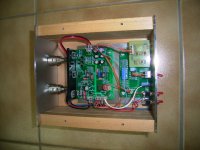
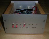
Another one done ...
I completed my 'Kelly Controller' and wanted to share some pictures and say thanks to all involved in getting this done. When the effort started, I did not imagine how big an improvement this controller is ! Bas - you should reconsider and complete the project. The BIX turntable improves a lot, the bigger diameter pulley and the controller cause a very noticable improvement. The sound is even more detailed, and the bass has a lot more 'clean' punch.
Thanks Mark for sharing this design with us and for providing the boards. Thanks Dave for getting the pulleys done - I ended turning my own in order to keep my motor housing and overall high as it was before ! Thanks superhkm for getting the Maxons. Thanks Algar_emi for sharing your project - it provided some inspiration for my housinghousing and finally thanks to all who participated - your comments, ideas, questions and answers were a big help in getting this device built.
Best regards,
Andreas
Attachments
- Status
- This old topic is closed. If you want to reopen this topic, contact a moderator using the "Report Post" button.
- Home
- Group Buys
- Who is interested in a groupbuy of Mark Kelly's DC controller PCB and related parts