I always wanted to say something but didn't know what to say...
My latest project is my headphone amp, the latest schematic can be found below. I have a working prototype!
http://www.diyaudio.com/forums/head...phone-amp-jlh-output-stage-8.html#post2306684
We can talk more elsewhere, I don't want to threadjack.
- keantoken
My latest project is my headphone amp, the latest schematic can be found below. I have a working prototype!
http://www.diyaudio.com/forums/head...phone-amp-jlh-output-stage-8.html#post2306684
We can talk more elsewhere, I don't want to threadjack.
- keantoken
Help Please!
Hi again guys. I'm trying to make single sided PCB for the final schematic of the amp but results are very bad... . I saw some PCB's in other threads and they look very very good compared to my trials. So I will need your help again to create one compact and very good looking PCB. I just can't make the stupid drawing.
Thank's to everyone who will help!
Hi again guys. I'm trying to make single sided PCB for the final schematic of the amp but results are very bad...
. I saw some PCB's in other threads and they look very very good compared to my trials. So I will need your help again to create one compact and very good looking PCB. I just can't make the stupid drawing.Thank's to everyone who will help!
I found that DipTrace is a very intuitive free PCB package. If you want to make boards with just MS Paint or some drawing program, you could ask OStripper here:
http://www.diyaudio.com/forums/solid-state/169590-mongrel-supersym-ii-13.html
PCB making is overwhelming I have found, I am not quite sure how to do it myself.
- keantoken
http://www.diyaudio.com/forums/solid-state/169590-mongrel-supersym-ii-13.html
PCB making is overwhelming I have found, I am not quite sure how to do it myself.
- keantoken
post37.
Could you explain the operation of the feedback.
I seem to half remember seeing something similar a couple of years ago, but I cannot find it.
See post 19. Original idea is taken from that schematic.
Sorry to come back, but post19 does not explain the operation of the feedback.
I cant explain that also. I try it and I like it. I only can hear the difference between conventional NFB and this one but how it works I dont know. Result is more stiff and fast bass as I said before.
It increases Bass amplitude. It will increase the bass from speakers which ordinarily have less.
The effect can be controlled by placing a trimmer or potentiometer across the 470nF cap.
Values for C5 will vary depending on the bass response of the speaker, and so different speakers will respond the same. So it may not work best with all speakers without changing the value.
However this cap could also be used to compensate for the bass reduction caused by C10 and C1, in which case the effect is more independent of speaker parameters. For this one would have to measure the time constant of R7 and C1+C10, and match this with the time constant of R5 and C5. R18 is necessary to limit bass amplification so as to control DC offset.
- keantoken
By increasing bass it will also correct for bass phase distortions. Here is a link:
Input Capacitors for Headphone Amps
- keantoken
Input Capacitors for Headphone Amps
- keantoken
600:600 telephone transformer can be very wideband <600 drive into >600 load.
Don't let an impedance matched frequency spec stop you from trying one. Did I
give you potted and shielded Stromberg Carlsons in the original junk box or no?
Not like cap is the only way to eliminate a DC offset at the input.
If you wanna go full stOOpid, some other rediculous options: One could
abuse an optoisolator, acoustic, or even an ultrasonic piezo coupling...
There would be no DC across a spring reverb tank, for example.
I was gonna say chopper stabilized, but then remembered that circuit
is for precision DC amplification, not for eliminating it like servo...
Optimally for this feedback network:
C5*R5=R7*(C10+C1)
If this is not true, bass will be amplified or not relative to the input signal.
This does not take into account speaker bass response, so one might want to leave C5 too low, to increase bass. However breaking the above relationship may produce a product which will prefer certain speakers.
- keantoken
Hello again!
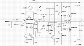
Hi guys again! I found a problem in my schematic.
After a loud play on a party amplifier burned the output devices. Amplifier was
hot and outputs were melt on the heatsink. So I replaced them and starting to play with multimeter attached to the amplifier. And now what I found - the source follower for thermal compensation does not work at all. Outputs have normal bias 100mA which can be adjusted with the trimmer but no thermal compensation - current start to rise after warm up. So my sourse follower didn't work. I replaced the gate to drain resistor to 3.3k and trimmer to 10k.
Now everithing works fine bias is very stable and amp works again.
If someone try to build that amp please be aware not to use the prevous schematic. There it is the corrected one.
Attachments
Last edited:
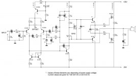
Update!!!
After careful listening tests i decide that amplifier sounds much better when VAS current is slightly increased. So I replaced bootstrap resistor 2.2k with 1.5k.
I think that will be the last update that I made to this amp.
And new schematic made with SPlan:
Best regards to everybody.
After careful listening tests i decide that amplifier sounds much better when VAS current is slightly increased. So I replaced bootstrap resistor 2.2k with 1.5k.
I think that will be the last update that I made to this amp.
And new schematic made with SPlan:
Best regards to everybody.
Attachments
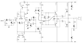
Your RF filter at the input is set very high (RC~0.05us).
Might be worth experimenting to find at which level it becomes audible? one octave lower, or two octaves lower, or three octaves lower, or a full decade lower, or four octaves lower?
Having reduced R17 from 2k2 to 1k5, it might be worth increasing C8 to >=100uF
What about Zener protection for the FET gates?
Last edited:
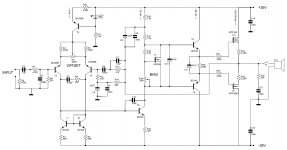
Tweaking....again???
Well a bit tweak to the VAS 68R is now down to 15R.
The more important is to reduce the compensation cap in the NFB from 22pF to 10pF or less if no oscillation in my case 10pF probably because no PCB everything is on a universal board and cables to drivers and outputs.
So I'm using the amp in this configuration over a month and no problem.
Sound improvement is amazing and I have many hours of enjoying it.
So till next tweak probably but when I don't know.
Attachments
Can you make a drawing to show me what you mean because I didn't understand your idea.
Actually this is my home amp that sounds really good and listening and enjoying it right now. I think it deserves a PCB and will try to make one but later maybe now dealing with this: http://www.diyaudio.com/forums/solid-state/199336-my-new-design-updated-old-one.html
Actually this is my home amp that sounds really good and listening and enjoying it right now. I think it deserves a PCB and will try to make one but later maybe now dealing with this: http://www.diyaudio.com/forums/solid-state/199336-my-new-design-updated-old-one.html
- Status
- This old topic is closed. If you want to reopen this topic, contact a moderator using the "Report Post" button.
- Home
- Amplifiers
- Solid State
- What you think about this schematic?