2sc3503.. or 2sc2690 (best)I'm not using KSE340 but BD139. Any advice for better transistor for that purpose?
OS
2sc3503.. or 2sc2690 (best)
OS
Is this also the best for driver, compare to MJE 340/350 gold pin, or BD 193/140?
thx,
Ervin L
Is this also the best for driver, compare to MJE 340/350 gold pin, or BD 193/140?
thx,
Ervin L
for 1 pair mosfet those would do. For more pairs or just better performance , mje15032/33 or 2sc4793/2sa1837 (super fast). BD's are low voltage , no good to me.
Some idiot designs run the mosfets direct off the voltage amp with "hot" MJE's, no drivers!!

OS
2sc3503.. or 2sc2690 (best)
OS
Nopes, Id say something like 2sd1508 or any other low to medium voltage darlington or super beta transistor. One super beta I have used is 2sc3964 which is specifically made for this purpose but the darlington solution does perform better though. This way there is no need for the resistor you and Andrew are contemplating. Note this is for the temp compensation only, not in the case of drivers.
Nopes, Id say something like 2sd1508 or any other low to medium voltage darlington or super beta transistor. One super beta I have used is 2sc3964 which is specifically made for this purpose but the darlington solution does perform better though. This way there is no need for the resistor you and Andrew are contemplating. Note this is for the temp compensation only, not in the case of drivers.
Just looked at the 2sd1508 .. gain of 4K ! I did notice an improvement going from the BDxxx/mje low gain to the 200hfe 2sc3503.So you say use a darlington?
At least the 1508 is to-126 ..
Would that not be overkill ? I have seen them used to Tcomp triples but that is it.
OS
Update made!
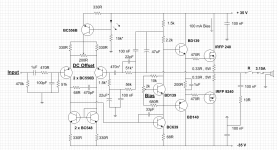
Well guys I make some changes to the amp.
1. Added Zobel and removed output coil.
2. Increased gate resistors to 470R
3. Corrected Bootstrap resistors to 1.5k and 2.2k
4 Added 100nF cap in parallel of the bootstrap 47uF cap.
There is some sound improvement - bass is deeper and tighter , trebles more clear and pleasant. Overall sound is better. I like it.
Thanks very much again guys for your good advices.
There is the new schematic.
Attachments
Last edited:
Just looked at the 2sd1508 .. gain of 4K ! I did notice an improvement going from the BDxxx/mje low gain to the 200hfe 2sc3503.So you say use a darlington?
At least the 1508 is to-126 ..
Would that not be overkill ? I have seen them used to Tcomp triples but that is it.
OS
Its mostly used on triples because here tcomp is more critical but it will have the same effect with EFs, one just has to decide if its worth the extra cost of the darlington. Well it can save on that resistor and less pcboard complexity. The 2sc3964 works pretty good and I would go this route for normal EFs, If I remember correctly they are 30v 500hfe minimum trannies.
Look at the left transistor in the current mirror. How much Vcb does this have? I would reduce the emitter resistors to 100R to give it higher Vcb and avoid saturation on volume peaks.
Also try increasing the 47uF cap to 470uF or higher. Just try a larger cap and see how it sounds, this will decrease bass distortion.
Connect the 22pF cap across both the 470n cap and 51k resistor. I like to avoid putting caps in series when possible.
- keantoken
Also try increasing the 47uF cap to 470uF or higher. Just try a larger cap and see how it sounds, this will decrease bass distortion.
Connect the 22pF cap across both the 470n cap and 51k resistor. I like to avoid putting caps in series when possible.
- keantoken
Look at the left transistor in the current mirror. How much Vcb does this have? I would reduce the emitter resistors to 100R to give it higher Vcb and avoid saturation on volume peaks.
Can you explain that better to me because I dont unedrstand what you want to tell me. I'm not that good at electronics so I will need additional info for this.
Thanks.
He means in the input stage: Mirror = 2 x BC548
There are two 330R resistors to help balance mirror.
If you reduce those to say 100R,
there will be less voltage across resistors and more voltage across those BC548.
If there is too little voltage across a transistor it will not work well.
*
VCB = voltage between collector - base
VCE = voltage between collector - emitter
VBE = voltage between base - emitter
Also try increasing the 47uF cap to 470uF or higher. Just try a larger cap and see how it sounds, this will decrease bass distortion.
- keantoken
If this is the bootstrap capacitor you re talking about,
as paradoxal as it may appears at first look, increasing
its value to 470uF will not increase performances, quite
the contrary......47uF is a good compromise...
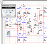
VCB 113 mV may be alright.
It is good to have at least 0.5 - 0.6 Volt from collector to emitter, node #4 to node #32
In other words, VCE should not be too far from 0.65 Volt. Especially not less.
It is also possible to use the mirror without R24 and R3.
This is often done.
When it comes to how much voltage drop across such resistors
it seems like it is often less than 100 mV.
If the current is 1.5 mA, this means those two resistors should be 68 Ohm or less.
One way to determine is to change value of resistors
and see how it affects THD distortion.
And change again.
The purist in me wants to wrap C9 around both R5 and C5. Wanted to say this earlier, but forgot. :/
If you are adventurous you could try using a photoflash cap for C1. I did this for my headphone amp and liked the results.
Congrats,
- keantoken
PS Hey Lineup! it feels like we haven't talked in years!
If you are adventurous you could try using a photoflash cap for C1. I did this for my headphone amp and liked the results.
Congrats,
- keantoken
PS Hey Lineup! it feels like we haven't talked in years!
Keantoken. Actually it is less than 2 years.
Because it was after my mother died.
I work and explore and design with Spice Sim every day.
There are things I want to publish. But better investigate more and more times, than to publish something that wont hold for an examination.
You better be sure you are correct
or you will have to get the pain of being corrected.
- Status
- This old topic is closed. If you want to reopen this topic, contact a moderator using the "Report Post" button.
- Home
- Amplifiers
- Solid State
- What you think about this schematic?