Some problems to work on:
For a tracking B+ design, one wants to use a tube that can work with minimal voltage across it, and also provide isolation form B+ to audio out. That leaves out most triodes. Many TV Sweep tubes can operate full current down to the 50 or 60 volt knee region (using maybe +120V on the screen grid), and have reasonably high output Z (for isolation from B+, compared to triodes).
Maybe you don't want full rail tracking, using multiple supply rails in 2 or more steps, start from lowest possible plate volt (say 60, 100, 150). The output tubes certainly need bias supply stepping as well. The gain and distortion need to be maintained under each step. In Sim of 6c19p otl (with positive feedback) distortion ranges from 0.05% to 1% when bias is stepped as well. JB has few articles on Class G tube OTL amp:
Hard-Core OTL Amplifier Design
Usually those stepped B+ schemes require more tubes to select each V rail, although a Mosfet could provide that function.
If one uses a variable PWM conversion for B+, then that tracking can come automatically (well, via a servo control).
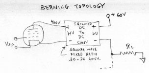
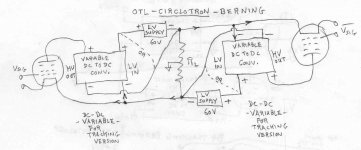
Just to clarify what the scheme is, some pics below of its derivation. First is the "simple" Berning "impedance converter". Just a fixed ratio DC to DC square wave converter. One used for the top P-P tube and another used for the bottom P-P tube (not shown). The load is driven by the converter LV side currents.
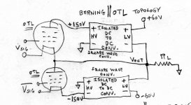
Next pic is the Berning scheme extended to include a parallel OTL setup. Since the tubes can handle direct load current, might as well use both tube and converter currents (they are directly proportional via turns ratio in DC to DC conv.). This is still using a fixed voltage square wave converter. Typical +/- 150 V supplies for full tube range operation. This will still make for a lot of heat, but the converter currents can reduce the # of tubes required by 1/2, so 1/2 the heat.
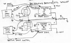
Finally, the tracking B+ Berning converter with parallel OTL setup. This now uses a variable PWM converter(s) instead of square wave type. The servo controls maintain the conversion output voltages at Vout +/- 70V, so the tubes operate with minimum voltage drop at all times. This should significantly reduce tube heat. The converter currents aid the tubes still.
After sleeping on this I realized that the variable tracking converters now also vary the converter current versus tube current as a function of the servo controls, since the DC to DC conversion ratio can change. Fortunately this variable ratio converter current increases the aid to the tubes when max output power is developed. So the tubes can be even fewer now, maybe another 1/2 as many. Heat developed should be quite reasonable now, since they also always have minimal voltage drop across them too. Probably needs to be modeled, but basically it is just making the tubes have a more aggressive "effective" gm curve. Considering that pentodes are already being used, some local N Fdbk is going to be called for, similar to CFB.
But now it is apparent that a simple PFC module won't work for the bottom converter. They have a direct connection from -LV in to -HV out. We need isolation there. So a true ferrite xfmr isolated converter will be needed.
Without the off the shelf PFC modules, this looks rather more complex to design. The PFC modules could still be used for a conventional Berning only type setup however.
Hmmm, late edit:
If the LV supplies are floated on Vout (like a Circlotron), the PFC converters should work, and the top one automatically adds 70V to Vout. No servo control needed! Woww! Even a square wave DC to DC conv. would work automatically then.
From impossible to trivial. Not sure about the bottom one yet, but looks like the PFC could be used then. OH, wait..... But then the LV side current doesn't add to the tube current for driving the load. It's isolated from the load then. Some more thinking required on this. Well, that should make the tube only fans happy I guess.
Yeah, just need some off the shelf 60V to 70V, or so, DC to DC converters, using floating (on Vout) +/- LV supplies to drive them. No servo needed, the internal constant V servo in the converters is already doing the job for us. But no LV current assist helping to drive the load then.
If one uses a variable PWM conversion for B+, then that tracking can come automatically (well, via a servo control).
Just to clarify what the scheme is, some pics below of its derivation. First is the "simple" Berning "impedance converter". Just a fixed ratio DC to DC square wave converter. One used for the top P-P tube and another used for the bottom P-P tube (not shown). The load is driven by the converter LV side currents.
Next pic is the Berning scheme extended to include a parallel OTL setup. Since the tubes can handle direct load current, might as well use both tube and converter currents (they are directly proportional via turns ratio in DC to DC conv.). This is still using a fixed voltage square wave converter. Typical +/- 150 V supplies for full tube range operation. This will still make for a lot of heat, but the converter currents can reduce the # of tubes required by 1/2, so 1/2 the heat.
Finally, the tracking B+ Berning converter with parallel OTL setup. This now uses a variable PWM converter(s) instead of square wave type. The servo controls maintain the conversion output voltages at Vout +/- 70V, so the tubes operate with minimum voltage drop at all times. This should significantly reduce tube heat. The converter currents aid the tubes still.
After sleeping on this I realized that the variable tracking converters now also vary the converter current versus tube current as a function of the servo controls, since the DC to DC conversion ratio can change. Fortunately this variable ratio converter current increases the aid to the tubes when max output power is developed. So the tubes can be even fewer now, maybe another 1/2 as many. Heat developed should be quite reasonable now, since they also always have minimal voltage drop across them too. Probably needs to be modeled, but basically it is just making the tubes have a more aggressive "effective" gm curve. Considering that pentodes are already being used, some local N Fdbk is going to be called for, similar to CFB.
But now it is apparent that a simple PFC module won't work for the bottom converter. They have a direct connection from -LV in to -HV out. We need isolation there. So a true ferrite xfmr isolated converter will be needed.
Without the off the shelf PFC modules, this looks rather more complex to design. The PFC modules could still be used for a conventional Berning only type setup however.
Hmmm, late edit:
If the LV supplies are floated on Vout (like a Circlotron), the PFC converters should work, and the top one automatically adds 70V to Vout. No servo control needed! Woww! Even a square wave DC to DC conv. would work automatically then.
From impossible to trivial. Not sure about the bottom one yet, but looks like the PFC could be used then. OH, wait..... But then the LV side current doesn't add to the tube current for driving the load. It's isolated from the load then. Some more thinking required on this. Well, that should make the tube only fans happy I guess.
Yeah, just need some off the shelf 60V to 70V, or so, DC to DC converters, using floating (on Vout) +/- LV supplies to drive them. No servo needed, the internal constant V servo in the converters is already doing the job for us. But no LV current assist helping to drive the load then.
Attachments
Last edited:
Rats,
the typical DC to DC converter regulates with respect to the (-HV out) terminal, not to the (-LV in) terminal. So the servo issue still needs to be addressed. Although hacking into an isolated converter, one could change the Vref tap point I guess.
Need (+LV in) connected to (+HV out) for the bottom side and (-LV in) connected to (-HV out) for the top side. Well, an isolated DC to DC conv. can still do that.
Those PFC modules already connect (-LV in) to (- HV out). Well that works for the top side at least.
A square wave isolated DC to DC conv. needs less filtering caps. Simple enough to design those. Once you have that designed, it works for either top or bottom. However, square wave converters are not generally regulated, just depending on the low resistance of the ferrite xfmr windings.
Argh! The HV to the tubes still need to be connected to output ground for the tubes to drive anything. So the +/- HV supplies really will have to be changing in magnitude. Constant isolated V converters -won't- work. Servos back in again. Back to the 3rd pic (above) again.
More thought needed on this obviously.
Well, this should be split to a separate thread if we want to continue this. I'm sure OTL advocates are getting tired of floating switching PFC supplies by now.
Last edited:
No output transformer in sight, go for it. FWIW the Atma-Shere circuit I'm using has a rail voltage of around 140 VDC. The supplies are completely floating and independent. Tubes banks aren't connected except at the speaker load. There are however 600 ohm resistors referencing the supplies to signal ground. The brainstorming is fascinating!
So, I re-thought the idea starting with "Circlotron" in capital letters.
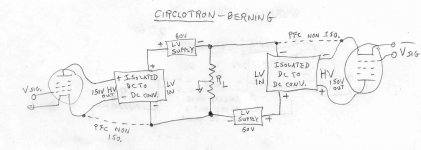
1st pic is the conventional Berning "impedance converter", but using the Circlotron configuration instead of the normal totem pole configuration.
2nd pic is Circlotron Berning and OTL together, both in Circlotron. HV supply in the traditional plate position. (the OR connection variant is possible)
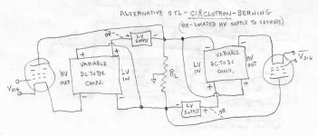
3rd pic is an alternative Berning and OTL combo, just moved the HV supplies to the tube cathodes instead. (the OR connection variant is possible)
What I notice is that pic 2 would allow -HV from the conv. to be connected to +LV of the converter. (the OR connection)
And that pic 3 would allow +HV from the conv. to be connected to the -LV of the converter.
The LV supplies could be moved around to the -LV inputs too, but seems a minor variant.
A converter that allows input side to output side connection, with sign inversion, is just an inverting class converter. (there are chip driven designs for these, using just an inductor) So this could be easily designed. Doesn't look like the PFC modules will work yet though.
There should still be another set of variants using Circlotron for one or the other (Berning or OTL) and totem pole for the other. I'll take a look, soon.
Trying to get -LV connected to -HV acceptable so PFC would work.
1st pic is the conventional Berning "impedance converter", but using the Circlotron configuration instead of the normal totem pole configuration.
2nd pic is Circlotron Berning and OTL together, both in Circlotron. HV supply in the traditional plate position. (the OR connection variant is possible)
3rd pic is an alternative Berning and OTL combo, just moved the HV supplies to the tube cathodes instead. (the OR connection variant is possible)
What I notice is that pic 2 would allow -HV from the conv. to be connected to +LV of the converter. (the OR connection)
And that pic 3 would allow +HV from the conv. to be connected to the -LV of the converter.
The LV supplies could be moved around to the -LV inputs too, but seems a minor variant.
A converter that allows input side to output side connection, with sign inversion, is just an inverting class converter. (there are chip driven designs for these, using just an inductor) So this could be easily designed. Doesn't look like the PFC modules will work yet though.
There should still be another set of variants using Circlotron for one or the other (Berning or OTL) and totem pole for the other. I'll take a look, soon.
Trying to get -LV connected to -HV acceptable so PFC would work.
Attachments
Something to sleep on:
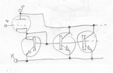
The Tube_Mirror.
Sometimes absurdly simple is just so much better.
No HF, no complexity, no cost (hardly any), no Watts (greatly reduced).
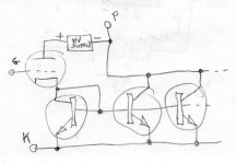
An nX current mirror is attached to a tube. Whatever current the tube draws, the nX mirror multiplies that current by nX. So you can reduce the # of tubes by n.
With a floating +HV supply just above the tube plate (in series), the operating voltage of the apparent mirror assembly can be reduced down to a practical 60V for driving a speaker efficiently.
The Tube_Mirror.
Sometimes absurdly simple is just so much better.
No HF, no complexity, no cost (hardly any), no Watts (greatly reduced).
An nX current mirror is attached to a tube. Whatever current the tube draws, the nX mirror multiplies that current by nX. So you can reduce the # of tubes by n.
With a floating +HV supply just above the tube plate (in series), the operating voltage of the apparent mirror assembly can be reduced down to a practical 60V for driving a speaker efficiently.
Attachments
Last edited:
Something to sleep on:
The Tube_Mirror.
Sometimes absurdly simple is just so much better.
No HF, no complexity, no cost (hardly any), no Watts (greatly reduced).
An nX current mirror is attached to a tube. Whatever current the tube draws, the nX mirror multiplies that current by nX. So you can reduce the # of tubes by n.
With a floating +HV supply just above the tube plate (in series), the operating voltage of the apparent mirror assembly can be reduced down to a practical 60V for driving a speaker efficiently.
I did that back in 2010, when we discussed similar solutions. It oscillated with triode connected 12L6GT, but in pentode connection worked just fine. I used resistors in emitters, for mirror ratio.
Please list these "compromises". Is it the outstanding frequency response? Low distortion with no feedback? I've probably got 100 hours on my monoblocks and they keep sounding better. I think having iron phobia is better than iron addiction.
quality triode will handle load itself, no problem. just give it high enough impedance.
high current tubes are often not much linear, lots of gnfb is needed.
the main point of tube work principle is lost, rather use transistors instead.
then there is this dc offset issue/dc servo thing, if amp has not output cap, speakers may pop.
best device for follower is transistor, so much gain and low internal z.
no tube can match it.
tube are naturally made as low current, high impedance devices.
you can convert lawnmower as vehicle to work, but it is far from optimal. it just excels in mowing
audio transformers must handle hifi range without problems, which is 10 octaves. often they can handle more.Please list these "compromises". Is it the outstanding frequency response? Low distortion with no feedback? I've probably got 100 hours on my monoblocks and they keep sounding better. I think having iron phobia is better than iron addiction.
comparing that to for example antenna preamps, it is huge wideband
Thinking about series connected speakers, which usually get mentioned for OTL. I noticed that a dual voice coil speaker, with the VC windings in series, give 4X the Zin. ( 2V/1I versus 1V/2I )
And, acoustically coupled speakers (front to front in phase, with series voice coils, acoustic suspension) give 4X the Zin.
So front to front phased, dual VC, speakers would give 16X the Zin. Or, 128 Ohms with just two speakers, not bad at all for OTL. And this still fits in an existing speaker cabinet.
128 Ohms is far higher than is needed for most conventional OTLs. 16 ohms is fine for most. The smaller ones might work a little better on 30 ohms, but that's about the limit.
Just to set the record straight, most of the above in practice is false:On the flip side, OTL:
Too many (usually matched) power tubes and a big power supply.
Too much heat dissipation.
Danger of speaker burnout or runaway tube destruction.
Requires plenty of N Fdbk. Circlotron included (just hidden).
Some kind of servo usually required to control the output offset Voltage.
Runs way too hot to consider real class A.
Uses high distortion tubes. Some of which are becoming extinct.
Not much options for a low (output) power OTL (with low power consumption, and tube count, to go with that).
We don't match power tubes and that does not seem to hurt things. Maybe too much heat for some, but I've seen class A amps that makes similar heat and power output.
There seems to be no danger of runaway tubes or damaging a speaker (or else we would not be in business after 41 years!). The only caveat is if the speaker used can't handle the power that the amp can make. If a tube arcs, its a DC event and if it also shorts, will blow the B+ fuse. This system is simple and reliable; so legitimate speaker damage by amplifier failure is really rare- so much so that after 41 years I can still count them all on one hand, with thousands of amps in service.
We don't run much in the way of loop feedback at all (4db on our smallest amp). No DC servo is needed- the DC levels are very stable and should be checked about once every 6 months.
The M-60 is in fact a class A2 amplifier into 8 ohms (Class AB2 into 4 ohms). Its best into 16 ohms FWIW.
The 6H13 is still pretty common, as is the 6C33 and both have good linearity. The pentode tubes are another matter, but generally I don't mess with them.
The Low Power OTL is a sort of holy grail. I've run just a pair of 6AS7Gs into a 16 ohm load with great results, but overall this is clearly a weakness of OTLs!
high current tubes are often not much linear, lots of gnfb is needed.
the main point of tube work principle is lost, rather use transistors instead.
then there is this dc offset issue/dc servo thing, if amp has not output cap, speakers may pop.
best device for follower is transistor, so much gain and low internal z.
no tube can match it.
tube are naturally made as low current, high impedance devices.
you can convert lawnmower as vehicle to work, but it is far from optimal. it just excels in mowing
audio transformers must handle hifi range without problems, which is 10 octaves. often they can handle more.
comparing that to for example antenna preamps, it is huge wideband
Again, most of this is false. We don't need GNFB to get THD at full power about 0.5%, with IMD at 0.05% or less, and we don't pop speakers, servo or not ('not' in this case).
Its important to have bandwidth from 2Hz to 100KHz at least, otherwise phase shift results with audible artifacts in the audio passband. This is one reason OTLs can play bass better than OT designs and sound more open and 3D while also being smoother and more detailed in the mids and highs.
All that said, I am interested in the alternative circuits mentioned recently, although I would not call most of them OTLs. An OTL will have no transformer and no semiconductors (the Berning amp, while a brilliant design, is not an OTL).
That is intriguing.
Would you still run it in a Circlotron config?
Which devices are you thinking?
Simple is nice...... PET240
The Tube Mirror scheme could be used in either a Circlotron or Totem Pole design. (or even for a P-P OT) It is a three terminal device, just like a tube.
Maybe use something like MJL3201A, lots of possibilities. Probably transistors with near constant Beta would be good. The IC circuit type current mirrors need matched devices, but for discrete devices one can roughly match them up and then put some 1 Ohm or similar emitter resistors under the transistors to match them up near exactly. Like when Roman Emperor Anatoliy... I mean, when Wavebourn used this in 2010.
One can also use just two transistors, with different emitter resistors, to get a current ratio mirror that is nearly as good. (uses up a little more B+ window)
MJL1302A is the PNP complement to MJL3201A if anyone is thinking of carrying this mirror scheme further.
Some smaller bipolars for use with non jumbo OTL type tubes are MJE15032G (NPN) and MJE15033G (PNP). There may be be newer variants out by now too. Other voltage ranges too.
(MJ... were Motorola part #s, probably similar parts from other vendors.)
Last edited:
And if done in a Circlotron one would not need complementary devices true?
Right
-----------------------------------
The Low Power OTL is a sort of holy grail.
With a 128 Ohm speaker (front to front phased dual VC bass speakers), it would seem possible to make a low power OTL (using just tubes, 1/4 the usual # of tubes).
Last edited:
One 6AS7G would do the job if that were enough power (about 10 watts).With a 128 Ohm speaker (front to front phased dual VC bass speakers), it would seem possible to make a low power OTL (using just tubes, 1/4 the usual # of tubes).
My speakers are 16 ohms and 98db 1 watt/1 meter. I often run just 4 6AS7Gs per channel (or two 6C33s...).
Into a higher impedance load, the amp will draw less power and make less heat- more of the power generated in the output section is dissipated in the load rather than the output section. Not much point in going over about 30 ohms IME.
But with 128 ohms, you could use 6SN7s if you had enough efficiency. Sometimes I drive my speakers with my preamp directly. The preamp employs two 6SN7s arranged in a Circlotron output and will play the speaker with no apparent distortion (or bass impairment) to a conversational level...
Yeh I'm still trying to get my head around that description of speaker configuration.
Just two speakers mounted front to front (facing each other), and put into the same speaker cabinet mounting hole. Then the voice coils are connected in series so that they are still acoustically in phase. (so one VC reversed) Now both speakers track each other's motions in the low frequency range. (insignificant sound propagation delay between the cones)
So the air in between them is neither compressed nor expanded, just pushed around as if the cones were connected. This effectively just makes the two speakers act as a single one with dual voice coils (and series connected for 4X Zo) Can also think of the cones being loaded on one side only, instead of the usual both, for each speaker.
Using dual voice coil bass speakers in the first place gives another 4X the Zo for each of those speakers. So both techniques together act like a 4 voice coil speaker, all connected in series for 16X Zo.
-------------------------------------------------
But with 128 ohms, you could use 6SN7s if you had enough efficiency.
With 3000 uMhos gm, the 6SN7 would make a 333 Ohm cathode follower, and twice that, 666 Ohm, in Circlotron. Not a very good damping factor with 128 Ohm load. And hardly the usual 5X Zout loading considered for low distortion triode loading.
A 21000 gm 10 Watt 12HL7 would make a 48 Ohm follower, 96 Ohms in Circlotron mode. A few of those in parallel could work well into 128 Ohms load.
Last edited:
- Home
- Amplifiers
- Tubes / Valves
- What tubes for a OTL tube amp?