
Not offended, just feel like our choices are getting thrown in our faces.
Dude you will likely have forgotten more about electronics than I will likely ever know.
Your Tower II and III look cool, but I have no clue about how they sound, but if I was wanting to build a SS amps I would be in the SS threads.
I am curious about using SS CCS on the cathodes, setting up a SLCF driver using FET's but I do not know how to design those circuits. Your input there would be completely useful.
Good luck? Thanks, I'll need it to get the sand to work and not let the smoke out......
Just exploring alternative topologies, sometimes they lead to interesting developments. Tracking power supplies appear to greatly reduce the tube power needed.
Thinking about series connected speakers, which usually get mentioned for OTL. I noticed that a dual voice coil speaker, with the VC windings in series, give 4X the Zin. ( 2V/1I versus 1V/2I )
And, acoustically coupled speakers (front to front in phase, with series voice coils, acoustic suspension) give 4X the Zin.
So front to front phased, dual VC, speakers would give 16X the Zin. Or, 128 Ohms with just two speakers, not bad at all for OTL. And this still fits in an existing speaker cabinet.
Last edited:
I gave up vacuum tubes in OTL amps. Here is a nice "tube" with 9A/V transconductance.
https://www.wolfspeed.com/downloads/dl/file/id/959/product/222/c3m0075120k.pdf

otl- so many compromises, just for a "iron phobia"
But then you are describing a OT tube stage in an OTL thread.Nothing complicated at all. (just the explanation)
Nothing Hybrid about it either, except the "tracking power supply". It IS Tube output.
Cheap to make with a low cost power toroid OT.
Does not produce a heat wave, even in class A, and maintains a low damping factor.
Just a low power P-P tube amp using a small power toroid OT or current xfmr.
Only thing different is the secondary winding impedance is more like 0.1 Ohm.

otl- so many compromises, just for a "iron phobia"
Yes, because there are no compromises in an OPT....
otl- so many compromises, just for a "iron phobia"
Please list these "compromises". Is it the outstanding frequency response? Low distortion with no feedback? I've probably got 100 hours on my monoblocks and they keep sounding better. I think having iron phobia is better than iron addiction.
The low bass frequencies are where the OT has issues with magnetizing current. ("Local" N Fdbk can handle magnetizing current, OT not in "local" loop)
Possibly the high freq. end too, if phase delay is an issue for global N Fdbk, but "local" (OT not in loop) N Fdbks can handle that easily too.
For low signal level, the steel has reduced (100X) permeability, which permalloy pin striped laminations can fix, or the LEM module (low level HF bias) can fix that too. (or just use local N Fdbk to lower the tube output impedance).
LEM: JLTi EL34 and KT88 Amplifiers
---------------------------------------------------
The 128 Ohm bass speaker config. mentioned above can handle the low freq. end using an existing speaker cabinet. A small OT (maybe 4:1 turns autoformer) for the mid and high freqs. could transparently handle the rest.
The resulting 128 Ohm system would then need only a few parallel tubes (TV sweep or V reg. in Circlotron config.) to handle the whole system then with tolerable heat dissipation and low distortion. A class D tracking B+ could lower the tube heat by another 5X to 10X in addition.
----------------------------------------------------
On the flip side, OTL:
Too many (usually matched) power tubes and a big power supply.
Too much heat dissipation.
Danger of speaker burnout or runaway tube destruction.
Requires plenty of N Fdbk. Circlotron included (just hidden).
Some kind of servo usually required to control the output offset Voltage.
Runs way too hot to consider real class A.
Uses high distortion tubes. Some of which are becoming extinct.
Not much options for a low (output) power OTL (with low power consumption, and tube count, to go with that).
Just saying it is worth looking at in between possibilities. The D. Berning switchmode OT would be another possibility for removing LF magnetizing current, but not a cure all. I prefer the simplicity of just using low output Z from the tubes (local N Fdbk) or the LEM module ($1 Op Amp and a few R's and C's) They don't get hot, and they lower distortion too.
Last edited:
Requires plenty of N Fdbk. Circlotron included (just hidden).
Great answer! Can you please explain the above please so I grasp what you mean? What I think it means is the way the tubes are being used, cathode bias etc, each triode has its own local feedback? I'm trying to still get my head around this feedback thing. If that is the case, then there is likely not circuit that would not have a feedback loop of some sort?
Great answer! Can you please explain the above please so I grasp what you mean? What I think it means is the way the tubes are being used, cathode bias etc, each triode has its own local feedback? I'm trying to still get my head around this feedback thing. If that is the case, then there is likely not circuit that would not have a feedback loop of some sort?
Circlotron is 50% cathode feedback (CFB). This means that 50% of the output voltage variation appears below the cathode (and the other 50% appears above the plate). As a result of the CFB, the grid drive signal has to produce that 50% plus the usual grid1 to cathode drive. Any variation from the expected output (for that 50%) affects the drive to the tube, so the tube automatically reacts to any errors to fix it. This is the same as any cathode follower function, but with just 1/2 the output signal monitored at the cathode.
This Fdbk action would nominally produce a gain of 2 for the circlotron circuit, except for what grid drive portion is needed for the actual grid to cathode drive, so reduces that gain slightly. CFB is a good N FDBK method. Nothing wrong with that.
However, the 6AS7 only has a Mu of two already, so not much N Fdbk results from CFB in -this- case. (you may be ending up with a gain of like 1 stage with both plate FB and CFB ) Most of the N Fdbk is coming through the plate for this tube. But, say a PL509 tube, then the CFB would be working hard.
Last edited:
50 12HL7 (were $1) could get you a Gm of 1A/V.
That Gm figure for Mosfets is also usually spec'd at some high current. Probably needs some scaling down for the same currents as the tubes are handling here.
---------------------------------------------------------------------
But I am thinking of a new OTL topology. Tracking B+ can reduce the tube power dissipation dramatically via efficiency. No need to waste all the B+ across the tube all the time.
So instead of a fixed voltage PWMS B+ supply, we could use a pulse amplitude supply. A Mosfet switching into a ferrite xfmr from LV to generate the B+ on the HV secondary. But the LV return would go to the output line also in a way as to aid the tube current. A servo would operate the switching amplitude to maintain a near constant minimal B+ on the tube. (so the switcher is not a fully ON/OFF type, but rather an analog pulse level type) The tube draws whatever current it needs to get the correct output voltage versus its drive signal. So the switching servo will be actively reflecting what the tube wants for current output in order to maintain the set point B+. Since the switching part acts as a current source, the tube Zo will still be setting the voltage output level.
Net result would be the Mosfet analog LV switching servo carving out like half of the final output current, the tube the other. Although this ratio could be modified by using some turns ratio other than 1:1 in the ferrite core. The tube still sets the output voltage.
Each P-P tube would then have one of these pulse amplitude switching servo's to maintain that tube's minimum B+. The LV return for each servo switcher would return to the output in a way as to aid that associated tube also.
Obviously this is looking rather complicated. But if you include the original fixed PWMS B+ supply into the picture, we have just modified its mode of operation some.
Plenty of design work, with switching technology thoroughly embedded obviously. HF flyback PWM switching might fit well for efficient analog current control. Or a PFC (power factor control) module might already do just what is needed, (variable LV input to fixed level output HV, perfect! ) Can get those off Ebay for cheap. This might actually be quite practical.
Well, just an idea. We return your monitor to its regularly programmed material.....
.
Last edited:
Thank you gents, very informative.
Regards the tracking B+, would it also sample the input to the amp so it knows what's coming rather than trying to react to the changes across the tube, thinking along the lines of a pre-emptive feedback PID loop sorta thing,(that's how my head makes sense of it anyway).
If I follow you correctly, it would have to be fairly well tuned to avoid phase or timing issues yes? I may be wrong there, but it could be interesting!
Thanks again!
Drew.
Yes!
A PID controller could be do the job much better than a reactive Fdbk control. Those Tripath class T amplifier modules used just such a design. They set the whole digital output (class D, class T) audio industry on fire using that.
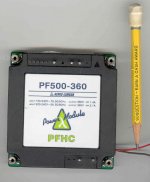
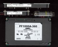
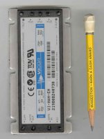
But from a DIY hobbyist perspective, those off the shelf PFC controllers look attractive (below).
Yes, the timing/phasing would be quite important for the audio purity.
One thing in our favor is the current ratio in the ferrite xfmr guarantees a constant ratio of tube current to LV switching return current. But any capacitance in the B+ circuit could smear that out some. And of course, the basic switching freq. needs to be filtered out. One could probably just put enough capacitance on the B+ to smooth out the basic switching pulses. So as long as the switching freq. is some multiple of the highest audio freq., we would be safe from smudging the audio.
However, those PFC modules don't use a full ferrite xfmr, they just use a charging inductor. I guess that still follows the same rules, or we would be generating power for free somewhere.
A PID controller could be do the job much better than a reactive Fdbk control. Those Tripath class T amplifier modules used just such a design. They set the whole digital output (class D, class T) audio industry on fire using that.
But from a DIY hobbyist perspective, those off the shelf PFC controllers look attractive (below).
If I follow you correctly, it would have to be fairly well tuned to avoid phase or timing issues yes? I may be wrong there, but it could be interesting!
Yes, the timing/phasing would be quite important for the audio purity.
One thing in our favor is the current ratio in the ferrite xfmr guarantees a constant ratio of tube current to LV switching return current. But any capacitance in the B+ circuit could smear that out some. And of course, the basic switching freq. needs to be filtered out. One could probably just put enough capacitance on the B+ to smooth out the basic switching pulses. So as long as the switching freq. is some multiple of the highest audio freq., we would be safe from smudging the audio.
However, those PFC modules don't use a full ferrite xfmr, they just use a charging inductor. I guess that still follows the same rules, or we would be generating power for free somewhere.
Attachments
Last edited:
Vicor makes some PFC modules too. I think they can be set up for less than 360V output too. (I see 250V to 400V on the module sticker, trimpot adjust) Probably other brands around too.
All of these PFC modules are non isolating from input to output (versus a real ferrite xfmr), which may be a problem for LV return current routing. Would have to sketch out a circuit to see.
The non-isolation of the PFC modules is also a safety issue for trying to get regulated B+ directly from the power line, a more typical application. Some DIYer's have considered these before, but usually lose interest once the non-isolation issue comes up. But for an OTL amplifier design, we would be working from a LV supply which would be isolated.
Attachments
Last edited:
Some problems to work on:
For a tracking B+ design, one wants to use a tube that can work with minimal voltage across it, and also provide isolation form B+ to audio out. That leaves out most triodes. Many TV Sweep tubes can operate full current down to the 50 or 60 volt knee region (using maybe +120V on the screen grid), and have reasonably high output Z (for isolation from B+, compared to triodes).
The PFC modules around typically are using a BOOST converter topology, so they end up with higher voltage out than the max voltage in. 260V or 360V ratings are just too high to get efficiency from the tubes. Most OTL designs are already using just +150V. This might be something that could be hacked, since we could still be boosting from a LV of maybe 60V. Maybe just a different trimpot range would work.
The Vicor modules typically are using a variable freq. converter, this could be a problem if the freq. can dip down near the audio spectrum.
Last edited:
So these things are a sort of SMPS/Inverter front end, like the ones that generates the DC bus in a variable speed drive.
Have you looked into the SLCF circuit from Allen Wright? He bootstraps the anode and CCS's the cathode to keep the voltage across the tube constant. Least I think that is what it does. Been a while since I read his book.
Have you looked into the SLCF circuit from Allen Wright? He bootstraps the anode and CCS's the cathode to keep the voltage across the tube constant. Least I think that is what it does. Been a while since I read his book.
I don't have his book, but I think I have seen a follower placed above the active tube to control the plate to cathode V. (mainly for distortion control) The follower is eating up all the heat that way unfortunately, working from a fixed B+ above it. But it is a tracking B+ generator for the active tube, just not an efficient one.
Yes, these PFC thingies are a front end for bigger switching power units, designed so they draw instantaneous line current proportional to instantaneous line voltage. (so unity power factor, looking like a resistor)
As opposed to the usual cheapo PWMS (like many PC supplies) which just rectify the line V into a big cap, drawing very spiked current off the line. Making the power cord, house wiring, pole transformer, power lines, and utility generator inefficient. I think PFC units are mandated for power supplies above a certain wattage. I know if I look at the line voltage here with a scope, it is nearly flat topped from spikey current draw from PC, TVs, radios, ... Nothing like a sine wave anymore.
- Home
- Amplifiers
- Tubes / Valves
- What tubes for a OTL tube amp?