That's really great Thank you very much, I'm trying to look at the circuit diagrams more , it's a bit like learning to read music in an odd way, seems harder than looking at the physical thing at first , but necessary once you move beyond the simplest stuff
thanks for explaining what that cap might do, I think I'll try it but it also doesn't sound like it'll affect the sonics. cheers")
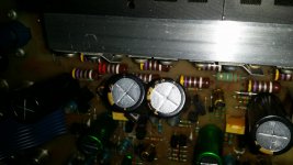
nice to know the polystyrene caps aren't knackered old rubbish too
thanks for explaining what that cap might do, I think I'll try it but it also doesn't sound like it'll affect the sonics. cheers
nice to know the polystyrene caps aren't knackered old rubbish too
nice to know the polystyrene caps aren't knackered old rubbish too
Surely they aren't! Polystyrene is/was among the top dielectrics with even better electrical properties than polypropylene. It's dielectric constant was lower than others', though, thus leading to relatively large capacitors. And it was expensive, compared to other dielectric foils.
Best regards!
every other cyrus I've seen myself or even seen pics of have had polypropylene and Polyester caps where those are but this example seems to predate the manual in a few regards. I suppose I could ask Mission if they have any info, this amp is staying "in the family" for sure so I don't mind putting a bit of effort into getting it singing
Caps on regulators are funny things. Having too large a cap negates many of the benefits of the regulator because it is the regulators job to maintain constant voltage, not the caps job to try and 'hold on to charge' an meet sudden demand.
In an application like this I would think a small value is all that is needed, just something to maintain a low impedance on the rail above the frequencies where the regulator performance falls off.
In an application like this I would think a small value is all that is needed, just something to maintain a low impedance on the rail above the frequencies where the regulator performance falls off.
Reading the comments on rough soldering and unusual caps, I think someone has already been in there and done the usual recap with fancier types and tried this and that tricks with components before you. I'm only saying this because it may affect judgement on what you see there and what might either be done better or redone as original.
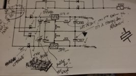
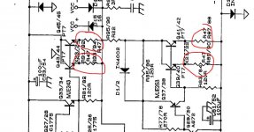
I need to compare the 06 circuit diagram with what I'm seeing on this 2's physical board. if there's a 22uF on one reg and not on the other I'll put one in.
I admit I did wonder if someone had been at this before but actually I don't think so. It's old but feels untouched and all the soldering (while copious and fluxy) is done the same on every single joint not just on caps , the lot !
I admit I did wonder if someone had been at this before but actually I don't think so. It's old but feels untouched and all the soldering (while copious and fluxy) is done the same on every single joint not just on caps , the lot !
Last edited:
The full Service manual for Mission Cyrus 2 amplifiers covers all 3 versions and has a separate schematic and parts list for 06. Versions 07 & TOG share a different schematic and parts list. Cyrus 2 - Manual - Stereo Integrated Amplifier - HiFi Engine
As expected, with the exception of C59 & 60 polyester caps, all film caps are specified as PP (polypropylene). If you find something else like polystyrene, polycarbonate etc. someone has done this later. Some electrolytic caps could be an upmarket brand now (Original Roederstein types and others were not good) and you may be able to decipher the date codes which will give some indication of when the work was done.
I think it likely that someone replacing every cap. in sight also resoldered every joint for good measure. As these were Taiwanese assemblies, I don't think cored solder flux would be left on connections unless the boards had been completely hand reworked without inspection, which would render them uneconomic anyway. The products were very clean and tidy when new, though I only recall seeing versions 06 and TOG.
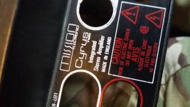
this differs significantly to the 06 in the cyrus 2 manual. The main on off switch is mounted to the front panel not on the board with a plastic linkage. I fixed my brother's 06 last year and it had a different circuit board layout to this one. It's clearly older than that one which was bought in 1985.
So ! I finally worked out that , at least working from the 06 circuit diagram , that c68 was missing. The regulated psu circuit is the same 06 , 07/tog. So i took the plunge and fitted a 22uF polarised cap to pair with c67.
Listening test followed the "didn't blow up" test and .... it sounds better !
which I did not expect , i thought it was related to the on/off behaviour etc.
but there it is , everything snapped into focus, previously i felt it sounded "splashy" , now sounds clear, clean and delicious. I ended up listening to it all afternoon despite much higher end gear being to hand. Result !

Hi again
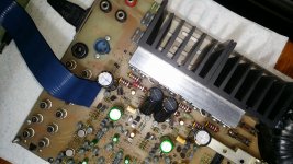
My early cyrus 2 project was running wonderfully on headphones but I'd no speaker cables with banana plugs. I stupidly thought it was finished, bht on testing at friend's it was a present for, it's quiet on one channel through the main outputs. I'm not suspecting the main selector switch or preamp as it sounds perfect on headphones, but I'd like to test the bias readings.
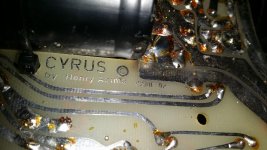
this very early model, issue 02 , possibly pre production, has no board markings and the oldest service manual i can find is for issue 06.
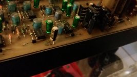
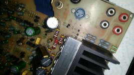
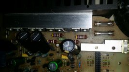
from the photo could anyone help me identify the resistors I could test for bias please?
My early cyrus 2 project was running wonderfully on headphones but I'd no speaker cables with banana plugs. I stupidly thought it was finished, bht on testing at friend's it was a present for, it's quiet on one channel through the main outputs. I'm not suspecting the main selector switch or preamp as it sounds perfect on headphones, but I'd like to test the bias readings.
this very early model, issue 02 , possibly pre production, has no board markings and the oldest service manual i can find is for issue 06.
from the photo could anyone help me identify the resistors I could test for bias please?
Attachments
My manual starts at 06 as well.
DC offset sounds fine at 7mv and 18mv. Bias problems alone would not alter audio levels, in other words with zero bias or high bias the amp would play normally.
I see in your picture what look to be 0.47 ohm resistors and that would correspond to the emitter resistors connected to the output transistors. Current could be calculated from the volt drop across one of these (no speakers attached).
Working on headphones and not speakers could be something simple like a duff headphone socket/switch. You would have to trace the circuit out and see how its done.
Attachments
- Status
- This old topic is closed. If you want to reopen this topic, contact a moderator using the "Report Post" button.
- Home
- Amplifiers
- Solid State
- What makes a good output transistor for Cyrus One