I swept the cable lengths to an extreme and noticed some possibly-interesting tendencies.
Firstly, this shows that there definitely is an effect, from bi-wiring. The parasitic L, R, and C are what is being increased. I happened to have those parameterized in terms of the length so I swept the length parameter because it was easy. But there are other reasons that the L, R, or C could increase, which might cause similar effects. Using thinner wires, for example, could mimic increasing the length, in terms of R.
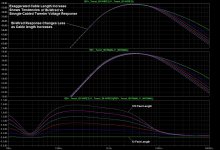
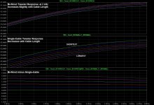
Another effect that was noted: Up until at least 6 kHz, the bi-wired tweeter voltage response changes much more slowly, as the cable length increases, than the single-cabled one; about one third as much per unit of length increase.
Also, up to about 6 kHz, the bi-wired tweeter's voltage response INCREASES as the cable length increases, while the single-cabled tweeter's response decreases (at 3X the rate than the bi-wired one's increases, as already noted).
The bi-wired tweeter's voltage response doesn't start to decrease vs the increasing cable length until between 5 kHz and 11 kHz.
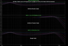
Plots are attached. The length increases that are noted in the plots (13 feet to 513 feet in 100-foot increments) would have increased the L, R, and C according to the values per foot that were used to model the 12-gauge "lamp wire" speaker cable: 1.7 milliohms of resistance per foot, for each wire of the two-wire cable, 0.19 microhenry of inductance per foot of cable (divided between the two wires, for simulation), and 21 picofarads of capacitance per foot of cable (from one wire to the other). A 100X increase of any of those is not very much.
Firstly, this shows that there definitely is an effect, from bi-wiring. The parasitic L, R, and C are what is being increased. I happened to have those parameterized in terms of the length so I swept the length parameter because it was easy. But there are other reasons that the L, R, or C could increase, which might cause similar effects. Using thinner wires, for example, could mimic increasing the length, in terms of R.
Another effect that was noted: Up until at least 6 kHz, the bi-wired tweeter voltage response changes much more slowly, as the cable length increases, than the single-cabled one; about one third as much per unit of length increase.
Also, up to about 6 kHz, the bi-wired tweeter's voltage response INCREASES as the cable length increases, while the single-cabled tweeter's response decreases (at 3X the rate than the bi-wired one's increases, as already noted).
The bi-wired tweeter's voltage response doesn't start to decrease vs the increasing cable length until between 5 kHz and 11 kHz.
Plots are attached. The length increases that are noted in the plots (13 feet to 513 feet in 100-foot increments) would have increased the L, R, and C according to the values per foot that were used to model the 12-gauge "lamp wire" speaker cable: 1.7 milliohms of resistance per foot, for each wire of the two-wire cable, 0.19 microhenry of inductance per foot of cable (divided between the two wires, for simulation), and 21 picofarads of capacitance per foot of cable (from one wire to the other). A 100X increase of any of those is not very much.
Attachments
Last edited:
In the old time, whether a capacitor is "in" the signal path or not was a big issue.
Only among people without a grasp of basic EE and among writers from audio comic books. Engineering types know what a transfer function is and how to determine it.
" A 100X increase of any of those is not very much."
I think gootee has again proven what we already knew. Yea, in a laboratory setting all these miracle solutions are measurable. In the real world, remember that the thermal effects on the voice coil and suspension have effects in the % range.
From an academic standpoint, fine. From an engineering standpoint this is the wrong place to be spending much time.
I wonder how many people have been sold bi-wire, or for than matter anything above zip cord, and have electrolytic caps in their speakers? The difference between $25 driver and a $50 driver is astounding. ( or $10 and 20 like the OEM pays). THAT is where an engineer goes to look.
My current project is trying to demonstrate that. It is a budget build using Silver Flute and Dayton. Cheap drivers that are better than most in-class. Can I pull off using them without eating up the savings in the crossover fixing problems better drivers don't have? Is the low crossover with big expensive coil cheaper than a more expensive driver you can cross higher? Do I have to raise the order of the crossover to keep away from breakup or tweeter LF distortion? I don't think a 3 mH coil is valid in a budget build, but neither is adding a notch for the breakup.
OK, got a chance to revisit my measurements, this time in differential mode.
Results:
The only difference I can find is maybe 1dB more low in the tweeter with single wire than with biwire. Frequency pairs used were 250Hz+8kHz and 186Hz+9.5Khz 4:1 amplitude ratio. Results were consistent thru multiple tests and rewires.
I don't know if this would hold with other amps, other speakers, other crossovers. Nothing else I measured was different. Not THD, not harmonics, not noise, not amplitude. A least for my system, it's hard to find any difference at all. FWIW & FYI
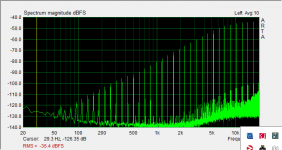
Looks more like 12 dB difference, at 35 Hz, and at least 4 dB up to 500 Hz.
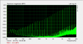
I saw some small THD differences, with LT-Spice, during two-tone tests. But they were probably all what I would call negligible.
Maybe try a loud 35 Hz tone and a soft 2 kHz tone and check the THD of the 2 kHz tone, for normal and bi-wired.
I saw some small THD differences, with LT-Spice, during two-tone tests. But they were probably all what I would call negligible.
Maybe try a loud 35 Hz tone and a soft 2 kHz tone and check the THD of the 2 kHz tone, for normal and bi-wired.
Last edited:

Tom (gootee) is on the right track - with the sort of audible effects that count in the subjective sense, one thing I can guarantee is that bog standard measurement testing will never, ever pick up anything that will seem significant.
There's an excellent analogy in the computing world: processors are staggeringly capable of doing repetitive, 'boring' digesting of data to the n'th degree of precision, they wipe the floor in a fair 'fight' with humans - but, ask the electronic wiz to find a meaningful pattern in there and they are reduced to a slobbering idiot. Bring on a 'dumb' human to look at the overall picture, and they immediately see the important element in the chaos of confusing, overwhelming information.
This is where the incessant call for 'real data' is totally missing the boat ...
But, there is a real answer waiting in the wings ... stop 'testing' gear in the magical belief that this will tell someone about how subjectively it will perform - and instead, test the 'testing'. Get 2 systems which are a perfect match in an ordinary sense, measurement wise - but which a few sets of good ears say are worlds apart - and then do nothing but investigate the testing mechansims. Not the systems, not the 'good ears' ... but the testing protocol itself. And keep going until there's a one to one correlation between the skilled listeners can pick up, and what the numbers say.
Then, we might start getting somewhere ...
Then, we might start getting somewhere ...
Only trouble is, these people seem somewhat 'close eared' - they don't connect too well to what the 'good ears' people are saying, about what they hear - that is at least the impression you get from comments made, by themselves and others expressing opinions about these people.
I may be being somewhat unfair ... but I feel that the researchers need to be as open minded as they possibly can be, if they are to get meaningful, and useful, results ...
I may be being somewhat unfair ... but I feel that the researchers need to be as open minded as they possibly can be, if they are to get meaningful, and useful, results ...
Sure. I will attach the .asc et al.
Thanks! unfortunately my travel laptop is unwilling to run LTspice for some reason, so will have to wait till I get home to play.
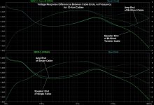
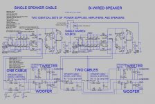
I noticed you are comparing voltages across the motional impedance portion of the woofer and tweeter, see Figure (A). Is there a particular reason you were doing this? Wouldn't it make more sense to be looking at the voltage applied to the drivers as in Figure (B)? Alternatively since cone velocity is proportional to current thru the voice coil, you could consider the current thru R12(tweeter) and R15(woofer) instead. Since far field response(SPL) of a piston driver is proportional to piston acceleration not velocity, you could multiply the currents by frequency to get acceleration if desired.
FWIW, the setup I used some years ago for comparing bi-wire vs single used two sets of 14 gauge wires(8ft long) running to the woofer and tweeter binding posts. A DPDT relay was wired in right at the binding posts so that the listening could remotely short the sets of binding posts together effectively choosing between between bi-wire or normal. Three buttons on the remote provided ABX testing. A= normal, B= bi-wire, X= A or B. If there were any differences, they were not enough for anybody who cared to try the test to determine if X sounded more like A or B for this particular test setup.
Attachments
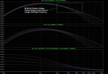
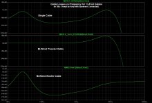
I forgot to post one obvious set of measurements from the LT-Spice simulation model that was used to compare bi-wiring to a single-cable speaker connection: Cable Loss sweeps. Attachments include:
- Voltage Response vs Frequency at each end of bi-wired tweeter cable and at each end of single cable, for 13-foot cables
- Loss in each cable, vs frequency, for 13-foot cables
- Loss in each cable, vs frequency, for lengths from 13 feet to 513 feet, with 100-foot increments
I also forgot to emphasize that all of the measurements and plots that I have posted could and probably would be different, and possibly very-significantly different, for every different crossover, cable, and amplifier.
Attachments
Thanks! unfortunately my travel laptop is unwilling to run LTspice for some reason, so will have to wait till I get home to play.
I noticed you are comparing voltages across the motional impedance portion of the woofer and tweeter, see Figure (A). Is there a particular reason you were doing this? Wouldn't it make more sense to be looking at the voltage applied to the drivers as in Figure (B)? Alternatively since cone velocity is proportional to current thru the voice coil, you could consider the current thru R12(tweeter) and R15(woofer) instead. Since far field response(SPL) of a piston driver is proportional to piston acceleration not velocity, you could multiply the currents by frequency to get acceleration if desired.
FWIW, the setup I used some years ago for comparing bi-wire vs single used two sets of 14 gauge wires(8ft long) running to the woofer and tweeter binding posts. A DPDT relay was wired in right at the binding posts so that the listening could remotely short the sets of binding posts together effectively choosing between between bi-wire or normal. Three buttons on the remote provided ABX testing. A= normal, B= bi-wire, X= A or B. If there were any differences, they were not enough for anybody who cared to try the test to determine if X sounded more like A or B for this particular test setup.
Thanks!!
I guess I had some vague notion that I would be plotting something proportional to the SPL, i.e. "the output" of the speaker.
Apparently I didn't understand the speaker models quite well-enough.
I will have to re-do some of the plots and see what kinds of differences it makes.
Current times frequency gives acceleration? Interesting! I'll have to try that, too.
Current times frequency gives acceleration?
Multiplying velocity by frequency is a shortcut method to get an output proportional to acceleration.
It basically tilts(or rotates) the curve up by a +6dB/oct slope.
See short article on displacement, velocity, and acceleration curves for a mass controlled dynamic driver posted here:
http://www.diyaudio.com/forums/multi-way/201226-drivers-behave-mass-spring-11.html#post2803717
Note the acceleration phase error mentioned by speakerdave in post # 120.
http://www.diyaudio.com/forums/multi-way/201226-drivers-behave-mass-spring-12.html#post2804212
Apparently I didn't understand the speaker models quite well-enough.
Perhaps you understand it just fine.
I just realized my comment about velocity being proportion to current is correct for the equivalent impedance model of the loudspeaker. However, you are using the equivalent mobility model where the current is representative of the force, not velocity.
I don't know off hand what circuit parameter would be representative of SPL for the mobility model, as I seldom deal with it.
I can look it up in Beranek tomorrow if nobody else beats me to it.
Sorry for the confusion.

Only trouble is, these people seem somewhat 'close eared' - they don't connect too well to what the 'good ears' people are saying, about what they hear - that is at least the impression you get from comments made, by themselves and others expressing opinions about these people.
The "closed ears" are that way because we understand that people are guillible and easily persuaded to believe in things that don't exist. Especially when the things that the "open ears" are claiming, have been contradicted by hard scientific knowledge.
I may be being somewhat unfair ... but I feel that the researchers need to be as open minded as they possibly can be, if they are to get meaningful, and useful, results ...
Having an "open mind" doesn't mean uncritically accepting ANY piece of nonsense that gets postulated as the key to audio Nirvana. Especially considering that typically it is getting people to waste time and money on, what are at best negligible factors, while ignoring sources of real improvements.
Making this worse is that the "fool's gold ears" refuse to accept ANY results or conclusions that don't support what ever their pet hobby horse is and just claim "oh, you're not GOOD enough to detect this difference that is blindingly obvious to me".
You might get taken more seriously if you could back up your claims with some evidence instead of vague suggestions as to possible mechanisms or showed some willingness to at least propose some standard of evidence you would accept as falsifying one of your claims.
Last edited:
If, by "DCR", you mean D.C. Resistance, how do you figure that's all you're seeing?
Take a look at the differences in the curves and how they scale with expected load impedance vs frequency. If you tweak the DCR up a little bit, I'll bet the curves overlay.
- Status
- This old topic is closed. If you want to reopen this topic, contact a moderator using the "Report Post" button.
- Home
- Loudspeakers
- Multi-Way
- What does the crossover do differently when you bi-wire?