A few ideas to really step it up a notch in quality... If you do not already have amazing AC filtering, and you can afford it... Stack up X1/2 capacitors for around 100uf on the primary and use a CMC. That will eliminate boat loads of noise coming in. At the VERY least throw on an X2 .1uf cap.
Instead of going with really large PSU caps, more smaller ones, for low impedance will give you even more filtering after the transformer. However sound may vary from effects of different capacitors.
Skip the OPAMPs and choose some JFETs that work off of 15v +/- to give it a really nice discrete input buffer.
Do not knock Blackgates till you have heard them burned in for 500-600hrs. Plus depending on the situation you can just use the high quality N ones for good blocking, and bypass with teflon caps for actual signal.
The input capacitor is smart if you do not always know what your source is going to be.
Destroyer OS. said:A few ideas to really step it up a notch in quality...
The reason I want to keep cost below a certain amount is that it starts to get close to the price of the Hypex modules.
I want to achieve great sound from modest components.
I believe input cap won't be necessary because it's a symmetrical design, DC (if any) should cancel out at the outputs (hopefully!). So almost no DC should arrive to the speakers.
Well, testing will tell that.
I am not sure I understand the snubber scheme you are proposing. What do you mean X2 and X1/2 caps?
Atilla said:That is looking really good, I'd like to try it myself !
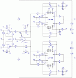
Just out of curiosity - any specific reason why the mute pins on the bottom LM chip aren't connected the same way as the one on top?
Hi Attila!
Thanks!
Well spotted it's a mistake. All the mute pins from both chip should connect to the resistor .
The mute pins should be connected correctly. Mute to ground means no music. Connect the Resistor to Vee and the capacitor with one end between resistor and chip and the other to ground. Look into the LM3886 datasheet for the right way to do it.
The outputs designation is wrong. If the postive signal goes into the inverting input, the output is negative, and the other way round.
The outputs designation is wrong. If the postive signal goes into the inverting input, the output is negative, and the other way round.
AndrewT said:Have you read Jung?
Particularly composite opamps and balanced signals.
DC coupled front end.
DC coupled back end.
Have you considered DC servo for the back end? or for both?
No input RF attenuation!
I have to admit Jung's articles are a bit too complicated for me. I don't fully understand them
Input DC & RF will be tackled with RC networks at the point of the XLR connectors
pacificblue said:The mute pins should be connected correctly. Mute to ground means no music. Connect the Resistor to Vee and the capacitor with one end between resistor and chip and the other to ground. Look into the LM3886 datasheet for the right way to do it.
The outputs designation is wrong. If the postive signal goes into the inverting input, the output is negative, and the other way round.
...quite right, thanks
AndrewT said:Have you considered DC servo for the back end? or for both?
I want to avoid that degree of complexity
I am using 0,1% resistors so no need for dc servos
- Status
- This old topic is closed. If you want to reopen this topic, contact a moderator using the "Report Post" button.
- Home
- Amplifiers
- Chip Amps
- Wendy200 a gainclone based on the BPA200
