AndrewT said:However, the vast majority in the Forum who have expressed an opinion on PSU RC claim that +-40mF for 4ohm speakers is far too much and does not result in improved sound. Some claim it kills the quality of the mid and/or treble frequencies. It is worth experimenting once you have you amps working.
I think if one uses a single filter cap per rail of the value of as big as 44,000UF, it will degrade the amp damping factor as impedance is too high. That is probably what people see as quality degradation.
If one uses 2x 22,000UF instead then the equivalent impedance will be 11,000UF (DF will quadruple in theory) but total capacitance is still 44,000UF, which is close to what you recommend.
So I think a good solution would be to use 22,000UF per rail into 8ohms to start with, and if someone wishes to use the amp into 4ohm they can add an extra 22,000UF per rail (along with changing fuses etc.)
Material: http://www.tnt-audio.com/clinica/ssps1_e.html
http://en.wikipedia.org/wiki/Damping_factor
Wendy200 PSU MK4
All,
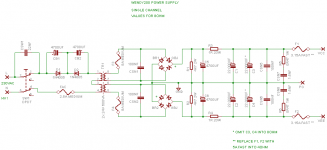
Thanks to your input, I have reviewed the PSU design - which is attached.
So I have taken it a bit further and it now includes:
a) A full CarlosFM MK4 PSU snubber scheme,
b) DC blocker on mains, as per DIYPARADISE to protect the transformer from DC, and
c) Optimised fuse values
I have not included a soft-start as I don't know how to design one, I will consider using it in the future.
To me it looks pretty much there, I am quite happy about how it's turned out
~ Any feedback ?
All,
Thanks to your input, I have reviewed the PSU design - which is attached.
So I have taken it a bit further and it now includes:
a) A full CarlosFM MK4 PSU snubber scheme,
b) DC blocker on mains, as per DIYPARADISE to protect the transformer from DC, and
c) Optimised fuse values
I have not included a soft-start as I don't know how to design one, I will consider using it in the future.
To me it looks pretty much there, I am quite happy about how it's turned out
~ Any feedback ?
Attachments
Re: Wendy200 PSU MK4
http://www.cantherm.com/products/thermistors/cantherm_mf72.pdf
chatziva said:
I have not included a soft-start as I don't know how to design one, I will consider using it in the future.
http://www.cantherm.com/products/thermistors/cantherm_mf72.pdf
Re: Wendy200 PSU MK4
As long as DC from your mains doesn't give you trouble, save your money for that DC blocker.
There is the saying "Don't cry before it hurts".chatziva said:b) DC blocker on mains, as per DIYPARADISE to protect the transformer from DC
As long as DC from your mains doesn't give you trouble, save your money for that DC blocker.
that DC blocker is wired incorrectly.
The two diodes should be wired in inverse parallel, not in series.
The tapping to the mid point of the series caps should be omitted.
A single pair of diodes will voltage limit at around 600mVpk to 700mVpk. If you need more voltage to prevent the small capacitors forcing the diodes to conduct during normal operation you can use 4diodes, each series pair are connected in inverse parallel. Go look at Peranders' site to see how to do it properly.
Remember the mains DC blocker is at mains potential, keep it away from probing fingers and tools and debris.
A very simple soft start can be made from a Power Thermistor in the live mains supply to the transformer primary. It's so easy to implement that it's not worth omitting. Look a Nelson Pass' site to see examples of implementation. I prefer a Power Resistor with a timed relay bypass, but that complexity can wait till you have the amp running.
The mains fuse is in the wrong supply lead. It must be in the Live lead.
Otherwise, when the fuse blows it leaves the equipment connected to Live but appearing to be dead. Now touch that chassis with the fault and you could be dead yourself.
The 8A fuses between secondary and rectifier do almost nothing to improve safety.
AndrewT said:that DC blocker is wired incorrectly.
I copied this design here and have also tried and seems to work okay. I will look at Nelson's Pass for a proper one anyway or might omit completely.
The 8A fuses between secondary and rectifier do almost nothing to improve safety.
But they are protecting the (extensive) PSU, no ?
Re post41 & 42,
I habitually use 10mF and 15mF smoothing caps. Banks of 20mF, 30mF, 45mF are built up to suit each amplifier.
Not terribly inventive, but they work.
The 4700uF caps before the resistor suffer extreme ripple current on high current draw from the PSU.
Either specify caps suitable for this extreme duty or use 5off 1mF high ripple caps paralleled to give an adequate ripple tolerant first smoothing.
AndrewT said:
no, the mains fuses are there to prevent the mains cables overheating and causing a fire after the amplifier has failed.
secondary fuses are there to minimise damage to the PSU and all upstream of the fuses.
The secondary fuses should be placed after the main smoothing and before you distribute the power around the amplifier. Most builders tend to place them at the amplifier PCBs, but that leaves the interconnecting wiring unprotected.
[/B]
no, the fuses protect the upstream side after the downstream side has gone faulty.quote:The 8A fuses between secondary and rectifier do almost nothing to improve safety.
But they are protecting the (extensive) PSU, no ?
it does not matter where it has been published, I still consider that it is wrongly wired.chatziva said:I copied this design here and have also tried and seems to work okay.
Re: Re: Wendy200 PSU MK4
Well my thinking was that a 600VA trafo will be subject to be more currents, so why not protect it.
It is an optional circuit as it is not part of the PSU board anyway
pacificblue said:
There is the saying "Don't cry before it hurts".
As long as DC from your mains doesn't give you trouble, save your money for that DC blocker.
Well my thinking was that a 600VA trafo will be subject to be more currents, so why not protect it.
It is an optional circuit as it is not part of the PSU board anyway
Re: Re: Wendy200 PSU MK4
That's neat ! I didn't know it can be that easy!
MJL21193 said:
That's neat ! I didn't know it can be that easy!
chatziva said:
That's neat ! I didn't know it can be that easy!
Yes it can be that easy, but if the amplifier is turned off and then on again in a short time after you might have a blown fuse anyway, because the NTC thermistor has not cooled of...
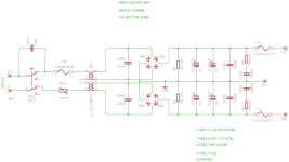
Here is the latest PSU design implementing a few changes:
1) Soft-start 10R thermistor on the AC mains line to limit inrush current. I plan to use one of these: SG27 or CL-60
Is the position of the thermistor correct?? In the CL-60 datasheet they are applied on the DC rails in series.
2) Big change: Removed the RC filter before the filtering caps for simplicity. This simplifies the PSU a lot as that resistor and cap were physically large plus the cap needs to have large ripple current rating thus difficult to find. The alternative of 5x 1000uf caps will take up a lot of space.
Will the effect of removing this filter be big or should I try to squeeze the 5x 1000uf in?
3) Removed the unnecessary 8A fuses
4) Simplified design by using 100nF snubbers all over
Attachments
CJ900RR said:Yes it can be that easy, but if the amplifier is turned off and then on again in a short time after you might have a blown fuse anyway, because the NTC thermistor has not cooled of...
...bad times. Good point!
enzoR said:can someone point out the purpose of the THS4131 to me. Why cant you directly feed the output of the LM4562 to the power amps?
http://en.wikipedia.org/wiki/Instrumentation_amplifier
http://www.univie.ac.at/cga/courses/BE513/Instrumentation/
In short, it helps common mode rejection, matches impedance and lowers DC offset - meaning no need for input cap (save space & money)
LM4780 footprint help!
I have been redesigning the amp modules and I have come across a strange problem.
I am using an LM4780 library which I have found somewhere in this forum.
The pads of the chip are wide, I want to reduce that width so that there is space for the copper traces to run in between the pins.
So I have rebuilt a package, symbol and device from scratch and used narrower pads.
But when I switch from schematic to PCB editor, the pads become thick again!!!
How can I correct that?
It's doing my head in!
PS: I am using Eagle btw
Quick update.
Due to the limitations of Eagle I have decided to use DipTrace for the design of Wendy200. Fantastic piece of software and very intuitive. Also quite not so difficult to learn.
The reason I haven't posted anything lately is that I am currently learning how to use it and designing my own libraries for the components. One does not actually have to do that as the libraries have everything!
So Wendy200 & PSU will be shortly with us.
Re: LM4780 footprint help!
You have to save that new component in a library. In the freeware version of Eagle however it is not possible to save it to an existing library. Workaraound is to save everything in a new library, e. g. save the former LMOPAMP.LBR as LMOPAMP2.LBR . In that library you can save the new component and use it from there.chatziva said:But when I switch from schematic to PCB editor, the pads become thick again!!!
How can I correct that?
Re: Re: LM4780 footprint help!
Nah tried that - still won't work. Don't know probably i'm doing something wrong.
I quite settled down with DipTrace now. Really neat program.
pacificblue said:
You have to save that new component in a library. In the freeware version of Eagle however it is not possible to save it to an existing library. Workaraound is to save everything in a new library, e. g. save the former LMOPAMP.LBR as LMOPAMP2.LBR . In that library you can save the new component and use it from there.
Nah tried that - still won't work. Don't know probably i'm doing something wrong.
I quite settled down with DipTrace now. Really neat program.
- Status
- This old topic is closed. If you want to reopen this topic, contact a moderator using the "Report Post" button.
- Home
- Amplifiers
- Chip Amps
- Wendy200 a gainclone based on the BPA200