For stability, as long as THS4131 alone is unity gain stable than wendy would be stable but since the feedback path is longer now to include LM4780, the parasitics might cause instability. You might want to add small film cap in parallel with the feedback resistor of THS4131 for extra compensation as precaution in case it is not stable.
Ipanema said:For stability, as long as THS4131 alone is unity gain stable than wendy would be stable but since the feedback path is longer now to include LM4780, the parasitics might cause instability. You might want to add small film cap in parallel with the feedback resistor of THS4131 for extra compensation as precaution in case it is not stable.
I agree about the gain. In the schematic the feedback path seems long but in the actuall PCB it's going to be very very short, so should be okay without the cap.
Evan

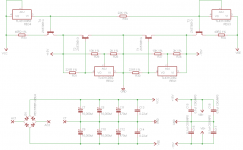
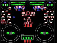
After quite a few hours in Eagle  I present you the draft Wendy200 PCB !!
It needs debugging as I missed some connections in the schematic but that's good I have found these errors now.
So the lot will be redone, probably during the weekend.
What I wanted to see from this quick (!!) assembly is whether the available routing space is sufficient (remember Eagle light poses a 100x80 mm limitation).
If I use 2x 22,000uf then space is enough. 4x caps cannot fit in there unless I do a separate power supply, which I want to avoid. I think 2x 22,000uf should be okay.
Note that the output part of the circuit is on the underside. That helps save some space.
There is a possibility to also put the shunt regulators on the underside and save space for 4x filter caps which must have slightly smaller diameter. Again I don't think that's necessary.
Any feedback on the PCB layout?
Evan
I present you the draft Wendy200 PCB !!It needs debugging as I missed some connections in the schematic but that's good I have found these errors now.
So the lot will be redone, probably during the weekend.
What I wanted to see from this quick (!!) assembly is whether the available routing space is sufficient (remember Eagle light poses a 100x80 mm limitation).
If I use 2x 22,000uf then space is enough. 4x caps cannot fit in there unless I do a separate power supply, which I want to avoid. I think 2x 22,000uf should be okay.
Note that the output part of the circuit is on the underside. That helps save some space.
There is a possibility to also put the shunt regulators on the underside and save space for 4x filter caps which must have slightly smaller diameter. Again I don't think that's necessary.
Any feedback on the PCB layout?
Evan
Attachments
enzoR said:can someone point out the purpose of the THS4131 to me. Why cant you directly feed the output of the LM4562 to the power amps?
Enzo
I am not an expert in op amps but a third op amp is traditionally used in most of the instrument amps.
The LM4562 provides the majority of the amplification, 2 in our case, and makes life for the THS4131 easier, which does some amplification i.e. 1.1.
The latter can be set-up to provide more amplification if needed in future.
Moreover I believe it helps common-mode noise rejection.
Evan
AndrewT said:With the on board PSU, you leave no flexibility to experiment with smoothing.
There is a lot of spare space on the PCB, might be good for low interference but bad for parasitics.
That is true Andrew, I think I will probably settle for a separate regulated PSU.
Another option is to add holes in the PCB for chassis mounted capacitors which are easier to find for capacitances of 22,000uf or 47,000uf - they will sit off board and connection can be with cables.
The PCB will get smaller eventually to avoid parasitics
Evan
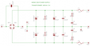
Wendy200 PSU complete
I have decided to ditch the onboard PSU and use a separate power supply for Wendy200.
I did not go for a regulated PSU as I think that type will be too stiff for a 200W amp.
So I settled for this unregulated snubberized design. One PSU will be used for each channel.
Features are:
- Designed for 10A mean or 14A peak current
- 22,000uf capacitance per power rail, 44,000uf per channel
- Noise filtering capacitors for AC and DC lines
- Snubbers
- Bleeder resistors
- 15A Fuses
The PSU will be matched with a 600VA 2x 25V centre tapped transformer for each channel.
PCB design coming soon!
Any feedback?
Evan
Attachments
Also thinking to incorporate this common mode choke in the PSU design but I am not quite sure how its 550R resistance will affect it:
http://uk.farnell.com/1503729/passives/product.us0?sku=tdk-acm1513-551-2pl
http://uk.farnell.com/1503729/passives/product.us0?sku=tdk-acm1513-551-2pl
Re: Wendy200 PSU complete
You should consider to move the fuses to the AC side. That way your transformer is also protected against shorts in the rectifier and on the PSU board.
Your transformer has a nominal current output of 600 VA/2/25 V=12 A. After stepping up the voltage with the capacitors, the current will go down accordingly, so you will get something between 8,5 and 9,5 A as maximum average current. Your fuses should be chosen accordingly to protect the transformer with slow to medium characteristics.
If you want to protect the electronic components, you need fuses with fast characteristics. The music signal will never demand continuous nominal output current. A first approximation is Imax/8, which would be somewhere in the 2 to 3 A range to start with. Then step them up, if convenience blowing occurs.
It will however interact with the capacitor and form a totally different type of low-pass filter, depending also on where you put it. Your snubberized PSU will probably not profit too much of it.
So many snubbers and you don't use any across the DC side of the rectifier directly across the diodes?chatziva said:Any feedback?
You should consider to move the fuses to the AC side. That way your transformer is also protected against shorts in the rectifier and on the PSU board.
Your transformer has a nominal current output of 600 VA/2/25 V=12 A. After stepping up the voltage with the capacitors, the current will go down accordingly, so you will get something between 8,5 and 9,5 A as maximum average current. Your fuses should be chosen accordingly to protect the transformer with slow to medium characteristics.
If you want to protect the electronic components, you need fuses with fast characteristics. The music signal will never demand continuous nominal output current. A first approximation is Imax/8, which would be somewhere in the 2 to 3 A range to start with. Then step them up, if convenience blowing occurs.
The 550 Ohms are at 100 MHz, so way out of the range, where they matter to your circuit. DC resistance is given as 4 mOhms, which is not too critical.chatziva said:Also thinking to incorporate this common mode choke in the PSU design but I am not quite sure how its 550R resistance will affect it:
http://uk.farnell.com/1503729/passives/product.us0?sku=tdk-acm1513-551-2pl
It will however interact with the capacitor and form a totally different type of low-pass filter, depending also on where you put it. Your snubberized PSU will probably not profit too much of it.
Hi,
look to use a T2.5A or T3.1A fuse for each transformer supply with a soft start.
Similarly, the output fuses should be reduced to F3.1A for 8ohm speakers or F5A for 4ohm speakers.
However, 22mF will not support extended bass for 4ohm speakers. It should be ideal for 8ohm.
look to use a T2.5A or T3.1A fuse for each transformer supply with a soft start.
Similarly, the output fuses should be reduced to F3.1A for 8ohm speakers or F5A for 4ohm speakers.
However, 22mF will not support extended bass for 4ohm speakers. It should be ideal for 8ohm.
Thank you all so much for your very very useful comments.
Summarizing your comments, I have come up with this list of improvements:
1) Use of 3A slow type fuses on each AC line to protect anything that's downstream the transformer
2) DC output fuses can be omitted but 3A or 5A are good values for 8ohm or 4ohm speakers respectively if one wants to use them
3) 550ohm @ 100MHz choke will not benefit the PSU substantially as it already has snubbers (but what about using those in the amp boards?)
4) Use of snubbers also on the DC side across the diodes (any values recommended?)
Any other opportunities for improvement?
Thanks
Evan
AndrewT said:Hi,
look to use a T2.5A or T3.1A fuse for each transformer supply with a soft start.
Similarly, the output fuses should be reduced to F3.1A for 8ohm speakers or F5A for 4ohm speakers.
However, 22mF will not support extended bass for 4ohm speakers. It should be ideal for 8ohm.
AndrewT which "22mf" cap are you referring to ? Do you mean the 220nf one that is across the AC lines on the rectifier bridge?
Also I don't understand why it will not support extended bass for 4ohm speakers. Still talking about PSU right? Can you explain it a bit more pls?
Thank you
Evan
Re: Re: Wendy200 PSU complete
Do you mean in parallel with each diode individually?
I plan to use a soft recovery type bridge rectifier for softer switching, so should not get too much diode switching noise.
Evan
pacificblue said:
So many snubbers and you don't use any across the DC side of the rectifier directly across the diodes?
Do you mean in parallel with each diode individually?
I plan to use a soft recovery type bridge rectifier for softer switching, so should not get too much diode switching noise.
Evan
secondary fuses are there to minimise damage to the PSU and all upstream of the fuses.chatziva [/i][B]1) Use of 3A slow type fuses on each AC line to protect anything that's downstream the transformer[/QUOTE] [/B]no said:2) DC output fuses can be omitted but 3A or 5A are good values for 8ohm or 4ohm speakers respectively if one wants to use them
The secondary fuses should be placed after the main smoothing and before you distribute the power around the amplifier. Most builders tend to place them at the amplifier PCBs, but that leaves the interconnecting wiring unprotected.
You have two 22mF smoothing capacitors. The same as the long winded way as stating 22,000uF.chatziva said:which "22mf" cap are you referring to?
Also I don't understand why it will not support extended bass for 4ohm speakers.
Search the posts for input filter, NFB filter and PSU filter and the relationship between them and how that in turn affects the performance of the speakers.
22mF with 8ohm =RC=176mS.
NFB filter should be<=176/1.4<=124mS.
Input filter should be <=124/1.414<=87mS.
This filter will be -1dB @~4Hz.
That is the normal lower limit to have least effect on the bass response of even small wideband speakers.
If you choose to use 4ohm speakers F-1dB becomes ~8Hz and this will be heard as attenuation of the bass of those speakers.
I usually recommend 160mS to 200mS for the PSU RC and for 4ohm speakers this gives +-40mF to +-50mF of smoothing for each channel.
If you have separate bass amplification and this amp only has to perform in the upper bass/mid/treble then you can change the input filter upwards to suit the duty and all the other RCs change with the input filter.
AndrewT thank you I am learning a lot from you.
I have searched but I can't find anything that shows that effect on speaker performance. Quite a lot of irrelevant results, can you direct me to some good ones?
I think I understand what you are saying now. From your previous posts, you recommended:
1) 160-200ms @ PSU
So this means :
a) 22,000uf @ 8ohm -> RC=176ms ok
b) 22,000uf @ 4ohm -> RC=88ms not good
c) 47,000uf @ 8ohm -> RC=376ms not good
d) 47,000uf @ 4ohm -> RC=188ms ok
In other words use 22,000uf filter caps / rail into 8ohm or
47,000uf / rail into 4ohm
If decide to use 2x 22,000uf paralleled / rail into 4ohm , is that equilavent to 44,000uf for the RC calculation AndrewT?
2) 130-150ms @ NFB
We already have a 1k NFB to GND resistor so if a 150uf cap is used then RC=150ms which is acceptable. (Now I understand why you recommended 150uf)
3) 90ms @ Input
a) 1k & 100uf -> RC=100ms marginal or
b) 1k3 & 68uf -> RC=89ms acceptable or
c) 2k & 47uf -> RC=94ms ok
Which combo is best?
Also why would one want to use that input filter at the first place if is to limit the LF content? What will happen if it's omitted (like in my case)?
Moreover when we refer to it as "input filter", do we mean just one filter per channel on the RCA or XLR connector (well 2 for the XLR)? Or one after the THS4131? Or 4 filters, one on each of the non-inverting pins of the power amps?
Lots of questions but we are getting there ... I really appreciate your and everybody else's help. Hope are answered so I can redesign it during the weekend! Excited!
Evan
AndrewT said:
Search the posts for input filter, NFB filter and PSU filter and the relationship between them and how that in turn affects the performance of the speakers.
I have searched but I can't find anything that shows that effect on speaker performance. Quite a lot of irrelevant results, can you direct me to some good ones?
22mF with 8ohm =RC=176mS.
NFB filter should be<=176/1.4<=124mS.
Input filter should be <=124/1.414<=87mS.
This filter will be -1dB @~4Hz.
That is the normal lower limit to have least effect on the bass response of even small wideband speakers.
If you choose to use 4ohm speakers F-1dB becomes ~8Hz and this will be heard as attenuation of the bass of those speakers.
I usually recommend 160mS to 200mS for the PSU RC and for 4ohm speakers this gives +-40mF to +-50mF of smoothing for each channel.
If you have separate bass amplification and this amp only has to perform in the upper bass/mid/treble then you can change the input filter upwards to suit the duty and all the other RCs change with the input filter.
I think I understand what you are saying now. From your previous posts, you recommended:
1) 160-200ms @ PSU
So this means :
a) 22,000uf @ 8ohm -> RC=176ms ok
b) 22,000uf @ 4ohm -> RC=88ms not good
c) 47,000uf @ 8ohm -> RC=376ms not good
d) 47,000uf @ 4ohm -> RC=188ms ok
In other words use 22,000uf filter caps / rail into 8ohm or
47,000uf / rail into 4ohm
If decide to use 2x 22,000uf paralleled / rail into 4ohm , is that equilavent to 44,000uf for the RC calculation AndrewT?
2) 130-150ms @ NFB
We already have a 1k NFB to GND resistor so if a 150uf cap is used then RC=150ms which is acceptable. (Now I understand why you recommended 150uf)
3) 90ms @ Input
a) 1k & 100uf -> RC=100ms marginal or
b) 1k3 & 68uf -> RC=89ms acceptable or
c) 2k & 47uf -> RC=94ms ok
Which combo is best?
Also why would one want to use that input filter at the first place if is to limit the LF content? What will happen if it's omitted (like in my case)?
Moreover when we refer to it as "input filter", do we mean just one filter per channel on the RCA or XLR connector (well 2 for the XLR)? Or one after the THS4131? Or 4 filters, one on each of the non-inverting pins of the power amps?
Lots of questions but we are getting there ... I really appreciate your and everybody else's help. Hope are answered so I can redesign it during the weekend! Excited!
Evan
Hi,
alternative values giving similar RCs are worth experimenting with.
Alternative RC values are also worth experimenting with, just like the low pass filter to attenuate RF. There is much leeway in the values, they are not set in stone!
If the DC blocking cap on the NFB develops a significant AC voltage then that results in distortion in the amp. A High Pass filter earlier in the system prevents this voltage developing.
If no filter is placed at the output of the source nor at the input to the receiver then that is effectively DC coupling on the input. I do not recommend mixed AC & DC coupling for an amplifier.
The PSU can be built up in many ways from low values of smoothing to high values.
The RC I have recommended came from others in the Forum and I found they worked for me. However, the vast majority in the Forum who have expressed an opinion on PSU RC claim that +-40mF for 4ohm speakers is far too much and does not result in improved sound. Some claim it kills the quality of the mid and/or treble frequencies. It is worth experimenting once you have you amps working.
- Status
- This old topic is closed. If you want to reopen this topic, contact a moderator using the "Report Post" button.
- Home
- Amplifiers
- Chip Amps
- Wendy200 a gainclone based on the BPA200