Salas,
Thank you for your response.
I have a .33uF PIO 630V as my coupling cap right now. I have also tried 2.2uF Obbligato Oil and 2.2uF Audio Caps.
The Audio Caps were provided with the Aikido board.
I disconnected the voltage supply to the attenuator and bypassed the board completely....still has a fuzzy sound to it. Not nearly as loud as I had thought it would be with NO attenuation... kinda low volume actually.
It must be on the Aikido Board somewhere......? I'll try A/C heaters later today, hope that works......
Ron
Thank you for your response.
I have a .33uF PIO 630V as my coupling cap right now. I have also tried 2.2uF Obbligato Oil and 2.2uF Audio Caps.
The Audio Caps were provided with the Aikido board.
I disconnected the voltage supply to the attenuator and bypassed the board completely....still has a fuzzy sound to it. Not nearly as loud as I had thought it would be with NO attenuation...
kinda low volume actually.It must be on the Aikido Board somewhere......? I'll try A/C heaters later today, hope that works......
Ron
Thanks for checking that out for me BW!
I pulled the C7-C10 (heater shunting) capacitors off the board and checked each of them separately .....too bad they are within specs. , I keep looking for the easy solution. LOL.
I tried A/Cing the heaters and enjoyed the hum they produced, but the fuzzy sound was still there. (still with the attenuator disconnected).
I pulled the coupling capacitors and will check all solder joints on the Aikido board with a jewelers eyepiece.
The hunt is ON!
Ron
salas said:There are also 0.47uF capacitors that feed psu ripple to cancel from B+ to second stage lower grid? Is there any DC leak there?
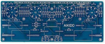
Salas, I have the PC board sold by J. Broskie, I have it torn down at the moment, but I will check when I put it back together. Thanks
boywonder said:This may be a dumb question; is the fuzziness in both channels?
BW, Certainly it it NOT a dumb question, and anything I can try is worth a shot. But, it is fuzzy in both channels. I have looked over the PC board and it looks clean....too bad. What's the chance of it being the tubes??? They are new and Provided by JB in the kit....I kinda doubt it's the tubes. New TungSols 6sn7s. Thanks for the thoughts!
Ron
I would suggest carefully rechecking the value of every single resistor and capacitor in the board, since it is on both channels this suggests an error performed in the assembly process or a power supply issue which is common to both channels.
Make sure there is no dc anywhere there is not supposed to be. I.e. Inputs and outputs of all boards used in this pre.
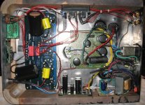
I also had to comment on what appears to be polystyrene foam inside the chassis, quite hazardous if flammable. Components sometimes fail, when they do they occasionally burst into flames or get extremely hot, contained inside a metal chassis this is not generally much more than an inconvenience, but add some fuel and you have a potentially dangerous situation.
Make sure there is no dc anywhere there is not supposed to be. I.e. Inputs and outputs of all boards used in this pre.
I also had to comment on what appears to be polystyrene foam inside the chassis, quite hazardous if flammable. Components sometimes fail, when they do they occasionally burst into flames or get extremely hot, contained inside a metal chassis this is not generally much more than an inconvenience, but add some fuel and you have a potentially dangerous situation.
Arnulf said:Renron, do you happen to own an oscilloscope or have access to one ? The wider the frequency range, the better. Short the input and observe the output for HF noise.
Arnulf, Thank you for your input, I do not own or have access to a 'scope. I wouldn't know how to read on if I did. Your comments are appreciated though.
")
salas said:Haven't made an Aikido, so I don't know it by board, but will be those leading to a couple of 100k resistors.
Salas, I will check into the caps. Thanks.
kevinkr said:I would suggest carefully rechecking the value of every single resistor and capacitor in the board, since it is on both channels this suggests an error performed in the assembly process or a power supply issue which is common to both channels.
Make sure there is no dc anywhere there is not supposed to be. I.e. Inputs and outputs of all boards used in this pre.
I also had to comment on what appears to be polystyrene foam inside the chassis, quite hazardous if flammable. Components sometimes fail, when they do they occasionally burst into flames or get extremely hot, contained inside a metal chassis this is not generally much more than an inconvenience, but add some fuel and you have a potentially dangerous situation.
Kevinkr, I have read many of your posts on other threads, they have always been from a foundation of experience and expertise.
I have removed all the caps from the board and have checked them with my Meter, all within specs. I will check the resistors tomorrow. I will check for DC voltage on the signal wires. Thanks.
I'm not sure if the foam is polystyrene as that is usually white as far as I know, but the hazard exists none the less. I will test a small piece outside and see how flammable it is. No doubt the fumes are toxic. The foam was placed underneath the relay board (no components on that side of the board) to aid in quieting down the relays. Any suggestions on a material for sound deadening
the relays? It was mounted on a rubber grommet to the case but still was very audible when relays engaged.
Thanks to all trying to assist me with this build. Much Appreciated!
Ron
Renron said:Arnulf, Thank you for your input, I do not own or have access to a 'scope. I wouldn't know how to read on if I did. Your comments are appreciated though.
Try to find somebody in your vicinity (ham operator, electronics enthusiast, etc., preferrably with a scope that is capable of displaying signals at least up to 100 MHz, the more the better). He'll know what to look for and how to go about it
HF oscillations are inaudible directly but they would affect performance of the amplifier, distorting sound further.BTW, I wasn't able to download your .wav file, it was as though the website was down (I did get the ad pop-up though ...) so I am guessing here.
Oscilloscopes aren't all that expensive (compared to the price of your amplifier), yet they are indespensable tool for locating problems. You should consider getting one and learning how to use it. I'm sure you can get second hand one pretty cheap.
OK, I have not tested this yet but I MAY have found out what I did wrong....
From Mr. Bas' PSU board the B+ (which is D/C) goes to the B+ marked on Broskies Aikido board. So far so good.
Here's where I think I made the mistake. I also took the - (negative) from Mr. Bas' PSU board to the Ground of the Aikido Board....Which is also the ground of the L&R Signal input.
I presume that the ground from the PSU board also carries a D/C current.........um, Yeah. Duh.....
I'ts my Wonderful Wifee's birthday today, and we're heading out to breakfast to meet out kids, so I'll put it back together after we get home. I'll post back if this was or wasn't the problem.
BTW, where does the ground from the PSU board terminate? Chassis earth I presume. Should I place a 20 R in series with it?
Thanks, I'll let you know if it works.......makes sense to me.
Ron
Renron said:I also took the - (negative) from Mr. Bas' PSU board to the Ground of the Aikido Board....Which is also the ground of the L&R Signal input.
I presume that the ground from the PSU board also carries a D/C current.........um, Yeah. Duh.....
Ron
If it is a symmetric supply (+/-) then its (-) is DC negative, and there must be some third connection for ground. If it is only +V supply, then its second connection is just ground.
My Aikido Hummed like crazy until I connected the ground from Bas' PS PCB to ground (and also to JB's boards). I have since added a 20 ohm 2w ground lift R to further reduce hum (PS ground and ground from vol pot connect to one end of the R, and the other end to ground. I am planning on adding a cap to the ground lift R when I get a chance.
Without the PS tied to ground, I blew my small test bench speaker in about 5 seconds due to the excessive hum. I now look at the signal out on the scope before connecting it to my bench amp, etc to make sure that the hum/dc offset is reasonable before connecting.
Without the PS tied to ground, I blew my small test bench speaker in about 5 seconds due to the excessive hum. I now look at the signal out on the scope before connecting it to my bench amp, etc to make sure that the hum/dc offset is reasonable before connecting.
Silence is Golden....Glowing
:l)
It was a grounding issue from Bas' PSU board to JB's Aikido Board.
I lifted the ground on JB's board and reference Bas' PSU with a 20R to Earth ground and Viola!
Thanks to all who helped out with responses and those who took the time to read this thread, I know you would have posted if you had any differing advice.
I could not have finished this build without the help of my fellow members of DiyAudio!
There is absolutely ZERO, HUM or BUZZ. Playing songs through the Curved Thors sounds outstanding. Fullness and detail that boardered on sharp, now sounds Rich, Lush (not the drunk kind of lush) and the presence and spaciality are worth my hard work.
Thanks again to all who helped me.
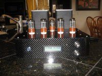
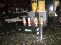
Gratitude, Photos follow.......upskirt with BIG Obbligato oil caps
Ron
:l)
It was a grounding issue from Bas' PSU board to JB's Aikido Board.
I lifted the ground on JB's board and reference Bas' PSU with a 20R to Earth ground and Viola!
Thanks to all who helped out with responses and those who took the time to read this thread, I know you would have posted if you had any differing advice.
I could not have finished this build without the help of my fellow members of DiyAudio!
There is absolutely ZERO, HUM or BUZZ. Playing songs through the Curved Thors sounds outstanding. Fullness and detail that boardered on sharp, now sounds Rich, Lush (not the drunk kind of lush) and the presence and spaciality are worth my hard work.
Thanks again to all who helped me.
Gratitude, Photos follow.......upskirt with BIG Obbligato oil caps
Ron
Attachments
- Status
- This old topic is closed. If you want to reopen this topic, contact a moderator using the "Report Post" button.
- Home
- Amplifiers
- Tubes / Valves
- Weird fuzz from Aikido Pre, HELP!