Hi Euro 21,
Thanks for your post! I used a very similar method (applying DC current from a high impedance source + AC coupled signal generator, measure AC reduction to obtain reactance and L) to test some Hammond chokes, where the values matched - but because of "clumpiness" disassembled the whole thing, so testing in a PSU was easier with the toroidys. But I will surely make a similar setup again, but less clumsy, like yours!
Main thing is, I contacted Toroidy, he agreed that there information on the website was not complete and made sure that it is better now. I think my tests and this thread are a step in the good direction of informing each other.
Be careful with the links as there is malware in both of them and you may get infected if using a windows based system.
How did you determine that ?
If you have doubts and are using Windows then take the time to do a couple of clicks and report it. (I found no problems by the way)
Attachments
Toroidy make really good transformers.
It's the chokes that are being discussed in this Thread.
It looks like the toroid based chokes cannot be made with a gap. That means DC and peak current has a big effect on the inductance.
I have no idea how one can saw a toroid core in half so that a gap can be inserted without all the laminations falling apart and/or springing back to their flat sections.I don't know what information was before on there site but what i read there now is that it is a AC choke and not a choke mentioned for a power supply where DC is involved.
So maybe the information they gave before was correct but maybe it was not clear enough that you couldn't use it with dc on it.
btw, There are toroids with a gap available to prevent such issues .
C-Cores are specially manufactured to achieve this gap with the pre-machined ends ready flat for an accurate gap.
I have no idea how one can saw a toroid core in half so that a gap can be inserted without all the laminations falling apart and/or springing back to their flat sections.
C-Cores are specially manufactured to achieve this gap with the pre-machined ends ready flat for an accurate gap.
??
I thought they were a ferrite "Cast"..perhaps I'm wrong.
Ie cast with a gap..
So if you overtighten them to the chassis you can crack the core..
Regards
M. Gregg
Last edited:
I have no idea how one can saw a toroid core in half so that a gap can be inserted without all the laminations falling apart and/or springing back to their flat sections.
Gapped toroids are nothing new and are very common now, lamination is impregnated with glue before cutting with band saw. Then pieces bonded together with non-sag epoxy.
Cut Cores
But any other (big)transformer company can do the same
But any other (big)transformer company can do the same
I have no idea how one can saw a toroid core in half so that a gap can be inserted without all the laminations falling apart and/or springing back to their flat sections.
C-Cores are specially manufactured to achieve this gap with the pre-machined ends ready flat for an accurate gap.
No, the induction is fluctuating to much for a crossover.
For very low dc levels in a power supply maybe
For very low dc levels in a power supply maybe
Big question now: what can I do with a 20H choke that can support 500mA of AC current. Maybe a line level crossover?")
Erik, what type OPTs you have bought from Toroidy ?
Any results ?
As I have previously told, I have tested two types of their PP OPTs with good results and just now ordered standard 10k (for ECL86 PP) and 5k PP, which will be custom made for me.
I have no experience about their chokes or SE OPTs. So far I am very pleased with their service.
Any results ?
As I have previously told, I have tested two types of their PP OPTs with good results and just now ordered standard 10k (for ECL86 PP) and 5k PP, which will be custom made for me.
I have no experience about their chokes or SE OPTs. So far I am very pleased with their service.
If you google and look at the cache then I don't see anything about DC current, so based on that it would seem that you were naive.
Dear mr Robbins,
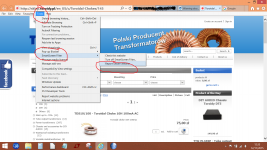
I learned a new trick today - no, it is not manipulating pics in photoshop - but to use the cache function. See the attachments, quite clearly stating "nominal DC current". But maybe you have seen something different?
When I wrote naive, it was referring more to the fact that I could know beforehand that there was something wrong with this info.
Attachments


Excellent sleuthing of google. Seems like they updated their website incrementally - no mention of AC in the title or that inductance would drop with DC in the simply accessed cached version.
The choke is probably fine for a normal choke input power supply application. You tested at 40VAC - were you able to test for inductance droop at higher levels consistent with a rectified AC voltage waveform for a B+ supply? The droop in inductance with applied AC voltage would indicate where saturation starts to become significant.
As a choke it may have a higher self-resonant frequency than a typical E-I type, and so give better attenuation above a few kHz.
I use Kaspersky.
Regards
M. Gregg
Anti virus companies are struggling to keep up with malware.
They now consider every new file to be a threat.
You have to get your software white listed to get through.
I write software and every time Norton and AVG throw it up as a virus when it isn't.
This means I get problems with customers who use anti virus that I haven't been white listed on.
Are you testing the choke with 120Hz ??? Do not use 1kHz or anything higher, since chokes usually have high winding capacitance that will monkey up the measurements...
You can test it in circuit a lot easier, unless if you have an inductance bridge with the ability to apply a DC bias current...
A gap is usually required for linearizing the inductor over it's operating range... Unless you are making a swinging choke....
The quick and dirty way to test it in circuit... Put a AC ammeter in series with choke and a AC voltmeter across it....adjust the BIAS of the power tube to vary the DC current...
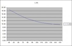
WHen using a DVM for the ammeter, just switch between AC and DC to note the measurements.. Your (AC Volts/ AC Current) will give you reactance... Divide by (2*pi* freq) to get INDUCTANCE... for 120Hz from a full wave bridge divide reactance by 377 ... Vary the BIAS of the valve from near cut-off to some high current that the tube can sustain for a just a short brief test... and note this DC current.. The true reactance you are getting is r+jw and you would normally vectorily subtract the resistance but most cases it is insignificantly small.. Make a graph of L vs DC current ... The applied AC ripple would be whatever you measure for your given amp and capacitor values.. If you use a scope to look at the current and voltages you can determine the Bsat point...
You can test it in circuit a lot easier, unless if you have an inductance bridge with the ability to apply a DC bias current...
A gap is usually required for linearizing the inductor over it's operating range... Unless you are making a swinging choke....
The quick and dirty way to test it in circuit... Put a AC ammeter in series with choke and a AC voltmeter across it....adjust the BIAS of the power tube to vary the DC current...
WHen using a DVM for the ammeter, just switch between AC and DC to note the measurements.. Your (AC Volts/ AC Current) will give you reactance... Divide by (2*pi* freq) to get INDUCTANCE... for 120Hz from a full wave bridge divide reactance by 377 ... Vary the BIAS of the valve from near cut-off to some high current that the tube can sustain for a just a short brief test... and note this DC current.. The true reactance you are getting is r+jw and you would normally vectorily subtract the resistance but most cases it is insignificantly small.. Make a graph of L vs DC current ... The applied AC ripple would be whatever you measure for your given amp and capacitor values.. If you use a scope to look at the current and voltages you can determine the Bsat point...
Last edited:
Are you testing the choke with 120Hz ??? Do not use 1kHz or anything higher, since chokes usually have high winding capacitance that will monkey up the measurements...
You can test it in circuit a lot easier, unless if you have an inductance bridge with the ability to apply a DC bias current...
A gap is usually required for linearizing the inductor over it's operating range... Unless you are making a swinging choke....
The quick and dirty way to test it in circuit... Put a AC ammeter in series with choke and a AC voltmeter across it....adjust the BIAS of the power tube to vary the DC current...
WHen using a DVM for the ammeter, just switch between AC and DC to note the measurements.. Your (AC Volts/ AC Current) will give you reactance... Divide by (2*pi* freq) to get INDUCTANCE... for 120Hz from a full wave bridge divide reactance by 377 ... Vary the BIAS of the valve from near cut-off to some high current that the tube can sustain for a just a short brief test... and note this DC current.. The true reactance you are getting is r+jw and you would normally vectorily subtract the resistance but most cases it is insignificantly small.. Make a graph of L vs DC current ... The applied AC ripple would be whatever you measure for your given amp and capacitor values.. If you use a scope to look at the current and voltages you can determine the Bsat point...
+1
Personally, I measured at 50 Hz and 100 Hz and then I would have said something. Not before that.
Hi Trobbins,
learned another new thing/word: sleuthing. An interesting word So I will try the choke in a choke input PS with low DC current, lets see what happens.
Cerrem and RajkoM,
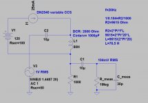
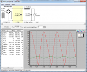
I tested the choke in the attached circuit, so at 100Hz, where I suppose it would work best. I started with 20H, and the ripple on C2 was minimal. Then I reduced the value of H until I came up with the ripple I actually measured, and this was about 1H at 150mA DC.
For previous tests, on Hammond chokes, I built a circuit similar to what Euro21 posted, and I plan to build a more definitive one soon, to test all sort of transformers under DC load. But the results of the test in the PS are, I think, quite clear that I tested the chokes before saying something? Also, the manufacturer now clearly states that under DC current the inductance will drop - he didn't say that before.
Funny that there are posts about Toroidy here at the forum, but very little actual results. I take the risk, buy the items, test and measure them, share the information, get the manufacturer to change the information on his product, and then I still get the impression that I am being the dumb one, not having done my homework?
Best, Erik
learned another new thing/word: sleuthing. An interesting word
So I will try the choke in a choke input PS with low DC current, lets see what happens. Cerrem and RajkoM,
I tested the choke in the attached circuit, so at 100Hz, where I suppose it would work best. I started with 20H, and the ripple on C2 was minimal. Then I reduced the value of H until I came up with the ripple I actually measured, and this was about 1H at 150mA DC.
For previous tests, on Hammond chokes, I built a circuit similar to what Euro21 posted, and I plan to build a more definitive one soon, to test all sort of transformers under DC load. But the results of the test in the PS are, I think, quite clear that I tested the chokes before saying something? Also, the manufacturer now clearly states that under DC current the inductance will drop - he didn't say that before.
Funny that there are posts about Toroidy here at the forum, but very little actual results. I take the risk, buy the items, test and measure them, share the information, get the manufacturer to change the information on his product, and then I still get the impression that I am being the dumb one, not having done my homework?
Best, Erik
Attachments
Funny that there are posts about Toroidy here at the forum, but very little actual results. I take the risk, buy the items, test and measure them, share the information, get the manufacturer to change the information on his product, and then I still get the impression that I am being the dumb one, not having done my homework?
Best, Erik
I think people simply are interested in your tests and findings about products from relatively new source.
Toroidal GOSS chokes (and gapped transformers) have one disadvantage - they (usually) have only one fixed size air gap in the core, made with band saw, and it can't be smaller then 0.5mm - 0.75mm unless cut with wire electrical discharge machinery. Other options possible if core is split into 2 or more pcs, but this is more complex, cumbersome and expensive process.
Adjusting air gap in toroidal core is not as easy as with C cores.
On the opposite side, today with modern machinery conventional cores can be manufactured with distributed air gap, programmable straight on the control panel.
Some chokes, such as fluorescent ballasts were designed for AC only, but are fine for use as chokes passing DC in amp power supplies - the main thing is to appreciate when the peak current level starts to get too far in to the saturation region - that peak current level can come from AC, DC or AC+DC, the choke doesn't mind at all.
To get good benefit from PSUD2 you need to appreciate what average L is likely to be presented for the current through the choke (PSUD2 doesn't model L variation). L versus current measurements are well worthwhile, and can be done in a few ways - the technique I use is in the link:
http://dalmura.com.au/projects/Choke measurement.pdf
Ciao, Tim
- Status
- This old topic is closed. If you want to reopen this topic, contact a moderator using the "Report Post" button.
- Home
- Amplifiers
- Tubes / Valves
- Warning about chokes by Toroidy