after a bit of investigation i would draw the conclution that my fet isn't switching. i sort of fixed it now, by refering my squarewave to gnd through a 20kohm resistor, but the readouts still puzzle me, the ones on my secondary side that is. i read squarewaves on both sides of the diodebridge, over the load rsistor. i figure i need to refere the secondary zero volt to gnd altso? gonna try.
altso you spoke of saturation and a-symetrical loading Eva, i'm afraid you lost me there, could you be so kind as to elaborate a bit?
thanks
marius
altso you spoke of saturation and a-symetrical loading Eva, i'm afraid you lost me there, could you be so kind as to elaborate a bit?
thanks
marius
Here's some information help you out. (Please do what Eva suggested and do some googling on push-pull primaries or flyback design)
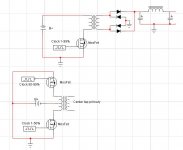
See attached image.
The top circuit (flyback desgin) is what your tring to build, if you build it that way in the schematic you should get farther than before.
In the second one is a push-pull desgin, as you can see there are two mosfets drive half of the primary hence push-pull, but this one requires that both mosfets NEVER turn on at the same time or they will cancel fields can cause a short circuit.
Check out this page for more on push-pull
BTW try driving the MosFet with 5-10V (the maximum voltage on the gate can be +/- 30V) of gate voltage, it may help your circuit better and if your using a signal generator you must put the ground with the ground and the positive on the gate of the MosFet or you'll get very crappy result or as Eva mentioned you'll blow it up.
Attachments
gnd from the siggen is connected to gnd from the psu, and gnd in the circut and the osciloscope. the "positive" (the squarewave is both positiv and negative referenced to gnd). is connected through a .22uf and has a 20k resistor to reference it to gnd.
ifrythings and eva, thanks for your tips, and thanks ifrythings for your schematics! i'm not completely ready to give up on the circut yet, but i'm gonna give your circuts a go.")
-Marius
ifrythings and eva, thanks for your tips, and thanks ifrythings for your schematics! i'm not completely ready to give up on the circut yet, but i'm gonna give your circuts a go.
-Marius
I'm gonna have to set up a gainstage in order for my to reach those signal voltage values. perhaps that will take some load off the siggen, i didnt like the waveforms i were getting out of it, think perhaps i was drawing to much current from it? the signal wasn't squarewaves anymore to put it like that.
bah, first vecation in years, the sun is shining, and my ski's are ready to se some action, and all i'm wanting is to get back to my smps
bah, first vecation in years, the sun is shining, and my ski's are ready to se some action, and all i'm wanting is to get back to my smps
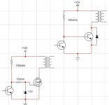
This should give you a nice gain factor (depending on transistor used) and the one with the mosfet has some protection for the fet incase it get too much gate drive.
This circuit must be driven with a square wave only (though you already know that right?), a sine wave will cause massive problems.
P.S I just notice that the zener value should be higher like 18V.
This circuit must be driven with a square wave only (though you already know that right?), a sine wave will cause massive problems.
P.S I just notice that the zener value should be higher like 18V.
Attachments
Hi.
I wanted to build an smps for a car amp, but was thinking on going further building it for a 120v ac mains for quasi's amp, I'll begin with esp projet 89 and advance from there.
Recently got some Vortex rectifiers that were going to the trash, and inside them there's a bunch of mosfets, diodes, capacitors and some nice (and big) ferrite transformers that i'm planning on using. I'll post something when done.
Figure i'l post a small uppdate.
i'm in the process of building a smps around the ua494pc i had lying spare. dunno what'l be used for, but i'l think of something.
the datasheet calls for a fullbridge, and so does my transformer.
finally got my veroboard, so i'm jumping forward a bit.
probably be asking you guys a lot of questions in the near future
-Marius
Mzruis,
DO keep us posted. There are a number of schematics for the TL494 available, so you should have no problem coming up with a good schematic.
Hey, I don't know, this might sound crazy, but how about making it power........ an amplifier.
Steve
DO keep us posted. There are a number of schematics for the TL494 available, so you should have no problem coming up with a good schematic.
i'm in the process of building a smps around the ua494pc i had lying spare. dunno what'l be used for, but i'l think of something.
Hey, I don't know, this might sound crazy, but how about making it power........ an amplifier.
Steve
Sometimes in life you get theese sudden realisations.
often theese are the kind that automatically triggers your hand to your face and a "DOH!" typy respons.
i just had one.
the bloody mosfet doesent open for anything less than 4Vgs.
why in the ninth circle of hell havent i been informed of this before?
here i'v gotten used to .65V as the standard of component activation, and pow, face slap.
i'm gonna give my old teacher a wegie for this
at least it clears up a thing or two.
-Marius
demogorgon said:
the bloody mosfet doesent open for anything less than 4Vgs.
why in the ninth circle of hell havent i been informed of this before?
here i'v gotten used to .65V as the standard of component activation, and pow, face slap.
-Marius
I did tell you
ifrythings said:BTW try driving the MosFet with 5-10V (the maximum voltage on the gate can be +/- 30V) of gate voltage, it may help your circuit better
also the .65V is for transistors and mosfets require several volts before they do anything.
Yes, you did. so you did.
I didn't make the connection between what i consdered to be a try-out-this type advice, and "mosfets need 4Vgs in order to open." that you said.
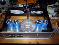
on another note, i may have hit jackpot recently:
the low resolution doesent really do the construction justice.
suffice to say, i'v found myself a bunch of sweet parts, and a new ampchassi
I didn't make the connection between what i consdered to be a try-out-this type advice, and "mosfets need 4Vgs in order to open." that you said.
on another note, i may have hit jackpot recently:
the low resolution doesent really do the construction justice.
suffice to say, i'v found myself a bunch of sweet parts, and a new ampchassi
Attachments
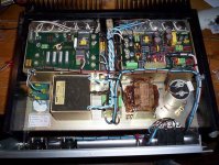
That, Eva, is a Eltek 20A, 48V smps.
norwegian buildt and produced, elna 3300\100v caps (huge) are on the bottom of the two pcb's. 5 caps i all.
the xformer is the square one, on the left, and one hell of an inductor is the one on the right.
gorgeus construction.
no controller ic though, based around the tl555 with a discrete circut.
it was a pleasure to dismantle, everything is just great, sturdy and no-nonsense. obviously not made in china to put it that way.
the case will se different use from now on.
Attachments
- Status
- This old topic is closed. If you want to reopen this topic, contact a moderator using the "Report Post" button.
- Home
- Amplifiers
- Power Supplies
- wanting to get into smps designing and building