Hey guys.
I'v caught myself sitting on my *** for to long, doing nothing.
for some time now i'v been loosing faith in the power waisting, overkill side of audio engineering, like gigant power burning class A amps, massive oversized transformer powersuplies and such. My interest has shifted to the more efficient, smart, but more complicated side of audio, like class D amps, dacs and smtp's.
as you can undoubtly guess i'm needing the final kick-in-*** to get moving into this field of DIY. i'v been googeling around, and looking in the forum for some simple ways to get started, but havent found the final extra to get me going, to re.
i was hoping some of you may have some links or such for me so i can start to explore this side of the pond.
my first project on this i was hoping to make a small 2-3 amp smps fron 230 to 12v, hoping to gain the final bit of overall understanding that i lack. i get the basics of trafo efficency rising proportional with frequency, up to the point of non-practicality, i altso have some understanding of general electronics, having buildt a gainclone or two, playing with tubes a bit, and designed and buildt a power\pre system microcontrolled as such. (including my "level of understanding so you hopefully will se better what i'm looking for.)
i would altso like to make use of scrap components as far as i can, having access to tons of such through school and work, and very limited monetary recources. i have access to lots of computer psu's, and smtp's from a lot of other appliences in general.
thanks
-Marius
Fixing mains powered stuff and designing stuff for mains power use is a completely different ball game. The ESP site has a 12V design, as I said I wouldn't recommend a mains powered one. Cut your teeth on something safe first ")
If you insist on offline converter, I contributed to a thread on here sometime in the past 2-6 weeks. You can find out how to take the philosophy of adapting the 12V powered ones to mains in there.
If you insist on offline converter, I contributed to a thread on here sometime in the past 2-6 weeks. You can find out how to take the philosophy of adapting the 12V powered ones to mains in there.
Totally different ballgame, yes, but still alike in the respect that the ball remains. a 12v smps just isn't much to cut my teath on, and besides, i dont have the parts required for it.
i'm not an idiot, and i take my precautions, so dont worry about that.
thanks for caring though.
i looked for the post you talked about, but i dont think i found it, if i did then it wasn't what i needed.
I'm not looking for the philosofy, i'm looking for the rock hard and real to put phiposofy into practical use.
still be glad for help
-Marius
Well... I will give you some ideas.
How about a half bridge? MOSFET or IGBT?
Voltage control (easy), peak current control (medium) or average current control (complex)?
Single output (easy), dual symmetric outputs for audio (medium) or several outputs (complex)?
Slow switching (30 to 40Khz) and low inherent EMI at the expense of bigger output capacitors and magnetics? or fast switching above 100Khz with small components at the expense of high EMI and high switch dissipation?
Do you feel like messing with an active power factor correction stage?
Also, do you have a mains isolation transformer, a variac and an oscilloscope?
demogorgon said:a 12v smps just isn't much to cut my teath on, and besides, i dont have the parts required for it.
So wrong. It's posts like that that make me say to people trying what you are, to take a step back. You make a 12V and mains SMPS in pretty much the exact same way.
demogorgon said:i looked for the post you talked about, but i dont think i found it, if i did then it wasn't what i needed.
I'm not looking for the philosofy, i'm looking for the rock hard and real to put phiposofy into practical use.
I did not put the philosophy in the thread, I put exactly what an engineer would need to do it. I suggest you keep looking, or start like I said with something that won't be dangerous. I'd like to build a fast car engine because that's what I want and need, but that doesn't mean I won't build some smaller ones to hone my skills first - it's not wasting time or parts, it's part of the necessary learning process to make sure that the big one doesn't go up in smoke and blow me up in the process.
Simple unregulated SMPS
Some years back I built a simple +/- 25V unregulated SMPS still happily humming along.
Being unregulated, it gets as simple as can be to debug and build, and being off line I used regular computer PSU rectifier, electrolytics and transformer. To keep things simple, I used a small inexpensive transformer to power the drive electronics (a quad gate, flip-flop and some transistors) instead of going for self-powered auto starting circuitry. Yet it even has a simple, capable overload protection.
If interested, I can post details, schematic and artwork.
Though I did not have isolation transformer or variac for developement, I should recommend them as safety precautions if possible. Be ready to burn some MOSFETS in the process.
Rodolfo
thanks for the replys! i was hoping you'd stop by Eva. what i'v seen from your post's here you seem to be vastly knowledgable on this and other subjects.
Richie, i take it you have some experience in this field as well?
I'l check out tomorrow what the IC in elliots project cost.
if it aint to much, i'l grab one, and start from scratch, without any execsive voltages.
salvages a humongous smps from a canon copymachine today, and there's 6 more of them in storage, waiting to be thrown on the heap.
it looks way good to be thrown away
on a slightly other note, what considerations need to be taken when designing a switchmode from scratch?
I have variac, scope and isotrans at school, but if i ask really nice... they have equipment for 15 students in the sound and picture department where i am, but since everyone is choosing car electronics theese days, we'r only 3 in my class. lots of stuff extra.
Gonna read up a bit, by the looks of it, it's just what i'm looking for
http://www.smpstech.com/
Re: Simple unregulated SMPS
Hi Rodolfo, you caught me typing
I'l gladly take the schematics, since you offer them
reccon i need all the input i can get, setting of to do the job of an educated engineer
-Marius
ingrast said:Some years back I built a simple +/- 25V unregulated SMPS still happily humming along.
Being unregulated, it gets as simple as can be to debug and build, and being off line I used regular computer PSU rectifier, electrolytics and transformer. To keep things simple, I used a small inexpensive transformer to power the drive electronics (a quad gate, flip-flop and some transistors) instead of going for self-powered auto starting circuitry. Yet it even has a simple, capable overload protection.
If interested, I can post details, schematic and artwork.
Though I did not have isolation transformer or variac for developement, I should recommend them as safety precautions if possible. Be ready to burn some MOSFETS in the process.
Rodolfo
Hi Rodolfo, you caught me typing
I'l gladly take the schematics, since you offer them
reccon i need all the input i can get, setting of to do the job of an educated engineer
-Marius
Texas instruments has loads of usefull stuff at their website.
http://focus.ti.com/analog/docs/training.tsp?familyId=64
APT's notes are not bad either, especially when you start to move to kW-range...
http://www.advancedpower.com/TechSupport/ApplicationNotesSP/default.aspx
More usefull stuff here...
www.st.com
www.fairchild.com
www.irf.com
www.infineon.com
http://www.powerint.com
http://www.powerint.com/PDFFiles/an15.pdf
...that should be enuff links for a while.
Re: Re: Simple unregulated SMPS
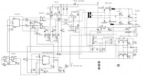
Here is the schematics. It is basically a square wave generator with dead time provision and a half bridge switch. Current sense on the supply rails provide device overload protection.
Rodolfo
demogorgon said:...I'l gladly take the schematics, since you offer them
Here is the schematics. It is basically a square wave generator with dead time provision and a half bridge switch. Current sense on the supply rails provide device overload protection.
Rodolfo
Attachments
Re: Re: Re: Simple unregulated SMPS
Tl494 rings a bell, think i have one left over from repairing a car amp.. on to the datasheets.
thanks
Thanks.
I'l be studying it.
richie00boy said:I have dabbled a bit in very simple SMPS.
The ESP project uses SG3525 which is a nice chip and cheap, but a lot of people use TL494 which seems even cheaper and easier to find. I suggest you start reading datasheets.
Tl494 rings a bell, think i have one left over from repairing a car amp.. on to the datasheets.
mzzj said:[snip..]
...that should be enuff links for a while.
thanks
ingrast said:
Here is the schematics. It is basically a square wave generator with dead time provision and a half bridge switch. Current sense on the supply rails provide device overload protection.
Rodolfo
Thanks.
I'l be studying it.
ingrast:
I like the way in which you have overcome the use of a control IC with some CMOS gates (even a gate oscillator )
There are a couple of improvements that I would do to that circuit. One is to place a 1uF non-polar capacitor in series with the primary of the gate drive transformer, as it's a better way to solve any potential saturation issue due to the drive signals being never exactly symmetrical. Currently, the transformer does not saturate only because severe flux imbalance causes excess current to flow in one direction and asymmetric voltage drop across R25, thus preventing deeper saturation. The capacitor will ensure almost perfect flux balance.
The other improvement is to add active gate turn-off to the secondary sides of the drive transformer instead of relying on primary controlled turn-off. The following figure shows a couple of ways to do it:
The simplest approach includes just R5, Q1, D2 and Q_IC_1 should be replaced by a diode.
Finally, that circuit relies on C4 and C18 for proper flux balancing of the power transformer. This is fine for an unregulated converter that always employs the same duty cycle, however, shall voltage mode regulation be employed, the dynamic duty cycle fluctuations with its related asymmetries would require a non-polar capacitor with a smaller time constant (1 to 10uF) in series with the primary.
I like the way in which you have overcome the use of a control IC with some CMOS gates (even a gate oscillator
)There are a couple of improvements that I would do to that circuit. One is to place a 1uF non-polar capacitor in series with the primary of the gate drive transformer, as it's a better way to solve any potential saturation issue due to the drive signals being never exactly symmetrical. Currently, the transformer does not saturate only because severe flux imbalance causes excess current to flow in one direction and asymmetric voltage drop across R25, thus preventing deeper saturation. The capacitor will ensure almost perfect flux balance.
The other improvement is to add active gate turn-off to the secondary sides of the drive transformer instead of relying on primary controlled turn-off. The following figure shows a couple of ways to do it:
An externally hosted image should be here but it was not working when we last tested it.
The simplest approach includes just R5, Q1, D2 and Q_IC_1 should be replaced by a diode.
Finally, that circuit relies on C4 and C18 for proper flux balancing of the power transformer. This is fine for an unregulated converter that always employs the same duty cycle, however, shall voltage mode regulation be employed, the dynamic duty cycle fluctuations with its related asymmetries would require a non-polar capacitor with a smaller time constant (1 to 10uF) in series with the primary.
Eva, Thanks for your interest.
True, in fact R25 does not show asymetrical drop, but I put it there as a malfunction safeguard. Though it is true the driving waveform cannot be perfectly symetrical, I divided the clock frequency by two to ensure that in a cycle by cycle basis it is almost nearly so. The little dead-time window provided by R60-C28 and R2-C1 help in allowing any residual flux to decay.
Agree also. Interestingly the converter runs (I don't recall exactly now) at about 100 KHz or more, yet swithching losses are extremelly moderate. When I built it I left it on 24 hs. with a 300W load and though it went hot, it was bearable to touch (no forced air cooling). In fact, the output rectifier was far hotter than the switching stage.
Rodolfo
Eva said:....One is to place a 1uF non-polar capacitor in series with the primary of the gate drive transformer, as it's a better way to solve any potential saturation issue due to the drive signals being never exactly symmetrical. Currently, the transformer does not saturate only because severe flux imbalance causes excess current to flow in one direction and asymmetric voltage drop across R25, thus preventing deeper saturation. The capacitor will ensure almost perfect flux balance....
True, in fact R25 does not show asymetrical drop, but I put it there as a malfunction safeguard. Though it is true the driving waveform cannot be perfectly symetrical, I divided the clock frequency by two to ensure that in a cycle by cycle basis it is almost nearly so. The little dead-time window provided by R60-C28 and R2-C1 help in allowing any residual flux to decay.
...The other improvement is to add active gate turn-off to the secondary sides of the drive transformer instead of relying on primary controlled turn-off. .....
Finally, that circuit relies on C4 and C18 for proper flux balancing of the power transformer. ....
Agree also. Interestingly the converter runs (I don't recall exactly now) at about 100 KHz or more, yet swithching losses are extremelly moderate. When I built it I left it on 24 hs. with a 300W load and though it went hot, it was bearable to touch (no forced air cooling). In fact, the output rectifier was far hotter than the switching stage.
Rodolfo
- Status
- This old topic is closed. If you want to reopen this topic, contact a moderator using the "Report Post" button.
- Home
- Amplifiers
- Power Supplies
- wanting to get into smps designing and building