two CRDs instead the 470ohm resistors (input pair's collector to rail), improve THD by 30%, mostly 2nd order.
Not the right place for CRD. 15k injection resistor can be replaced with CCS. 470 ohm determine input stage's voltage gain, so by replacing it with CRD would make extremely unstable and nonlinear transfer function. Sims swallow many unrealistic solutions.

Not fully satisfied with data i found about small heatsink for VAS i decided ti swap to ones well known and that i have in stock. Miller caps has swap to RF SMD type the more close i could to Vas transistors legs.
Good to use four 1mF as in sch. Nice PCB.

What do you mean? To combine two amps? Please elaborate Sonny.
At VSSA we are fixed to six transistors only, as promised.
Sorry i forgot about the thread saying only siz transistors.
The only reason to use this output section, is that the current is much lower in every part.
I think with your setting you are at about 20watt per channel instead of 4 - 8 watt per channel!?
But forget about what i have wrote.
I think with your setting you are at about 20watt per channel instead of 4 - 8 watt per channel!?
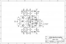
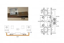
Two 50 kHz graphs clearly shows 50 Wrms/8 ohm at +/-32 V rails. Settings are: 1,8 mA input stage bias, 15 mA VAS bias, 100 mA output bias and all resistors values as in the VSSA 1.2 schematic. VAS transistors on the main heatsink, TLVH431 as bias spreader set to 1,565 V, Miller caps 12 pF.
regarding onboards caps
new develloped small lytics can have very low ESR and high current handling
I would say no poly caps needed, only one lytic cap per rail, thats all
and the VSSA board will look neat and simple
get rid of all those stupid caps
just my personal opinion on it, ofcourse
new develloped small lytics can have very low ESR and high current handling
I would say no poly caps needed, only one lytic cap per rail, thats all
and the VSSA board will look neat and simple
get rid of all those stupid caps
just my personal opinion on it, ofcourse
LC, can you please point to the schematic of the bias spreader using TL431. Thanks.
VSSA having VAS transistors on the main heatsink, because of the thermal considerations, require TLVH431 as bias spreader. Once bias is trimmed to proper value, 1 k trimmer can be measured and replaced with two fixed resistors. Vgg fixed to 1,565 V in my case, enabling 100 mA output bias current.
Attachments
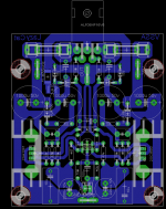
neat looking board
looking at small changes
if you move one lytic up, and make the other smaller, you might be able to shrink the board maybe 20%
maybe it would help to make it just 10mm wider
your Vas heatsink design appear somewhat 'space wasting' ?
maybe consider making 'optioanl' mountinghole, somehow
would make optional mounting on main heatsink possible
Attachments
well, since I have my own funny ideas...more to come
I'm planning to design specific VSSA PCB, maybe we are on the same track ...
two CRDs instead the 470ohm resistors (input pair's collector to rail), improve THD by 30%, mostly 2nd order.
Did you try to sim with 1N5297 or similar?
Question is thermal stability and VAS Iqc stability if 470 ohms are replaced.
Last edited:
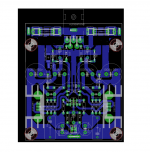
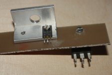
adding a small PCB...just to illustrate the basic idea
... so still small separate on-board heatsink for VAS. I'm planning to go to the main heatsink with VAS, just like in my test setup.
... so still small separate on-board heatsink for VAS. )
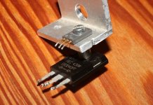
output source pins will be hardwired
... look at it 3 dimensional, instead of one plane output source pins will be hardwired
ALF pins connected to PCB with wires? Not very good idea.
- Home
- Vendor's Bazaar
- VSSA Lateral MosFet Amplifier