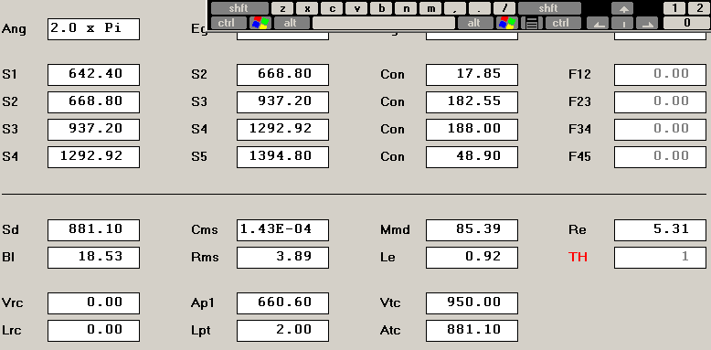
Did you do your own HR sim based on your actual build dimensions, or did you use the numbers from his site?The peak around 34Hz is interesting because HornResp didn't predict anything would be there. The peaks match predicted excursion within reason. That's why I think my parameters are messed up. Anyone else up for giving it it a run?
The horn shown in the original HR shot on the site does not math up to what is shown in the plans.
Can the THD measurement using REW be performed outside?QUOTE]
You can, but I was mainly asking about THD below the horn's passband (<20Hz). Indoors will get you some room gain which will make the measurements easier (less background noise), and it gives you numbers in the environment it will actually be used...Above 20Hz, it should play very loudly and cleanly by design....
I liked the comments about the slight difference in sound between the TH vs FLH....
JSS
I did use the parameters from his site to see how the 3015lf modeled. That would be the source of the discrepancy if they aren't representative of the plans.  Now I just have to figure out how to put the dimensions from my copy of the plans along with the 3015lf parameters into HR. What's the best way to go about reverse-engineering the dimensions into the program?
MaxMercy- Cool, When I get REW up and running with my SPL meter I'll try and knock out some numbers for ya, most likely by the end of May.
 Now I just have to figure out how to put the dimensions from my copy of the plans along with the 3015lf parameters into HR. What's the best way to go about reverse-engineering the dimensions into the program?
MaxMercy- Cool, When I get REW up and running with my SPL meter I'll try and knock out some numbers for ya, most likely by the end of May.

This is what I get, quick and dirty.
 Out-standing! Nice work grinding that out so quickly!
It does indeed match up quite closely now.
 I took some room measurements today (sans EQ) and was suspicious about the levels I was obtaining, which were hovering around 95 db. I couldn't get 2.83V to the driver cause the amp I was using was digital and had discrete indexing for the volume control. It was either 2.66V or 3.02V, so I used 2.66V. Even still, the results seem fairly close (given room interaction of course). When I get a chance to measure outside, then we'll really be able to make a solid comparison. Thanks for the hook-up Soho!
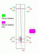
Had some people ask, so this is how you can figure it out.
In the center of L34 is an increase in size, so it should really be split into two different section. It is a minor increase, so it isn't that big a deal. The main problem is that there is no real flare for that portion of the horn.
I just noticed the little chamber at the bottom of the driver shortening L12. I didn't notice it last night. Subtract 8.9cm from L12 in what I posted before to add it back in. It cleans the impulse response up a little.
Attachments
Last edited:
Volvotreter 20 Hz Tapped-Horn subwoofer (video)
Video!! Listening with a good set of headphones will give you an idea of what the sub is doing.
Enjoy! It's been a hoot!
YouTube - 20 Hz Tapped-Horn Subwoofer
Video!!
 Listening with a good set of headphones will give you an idea of what the sub is doing.
Enjoy! It's been a hoot!
YouTube - 20 Hz Tapped-Horn Subwoofer
Last edited:
soho54 said:![url]](https://www.diyaudio.com/forums/attachments/subwoofers/167673d1271690893t-volvotreter-20hz-tapped-horn-build-pics-my-version.gif[/url]) How did you calculate S5-S6?
How did you calculate S5-S6?
I just did a quick calculation based on the plans from his site. The red lines indicate where the S positions should be. W x D. With S5 pretend the driver isn't there, and measure what the distance would be if there wasn't a hole there.
If you mean the distance, since the bend is 90deg I just connected the centers of the sections before and after the bend to better match a wave true path around a tight bend, just like the dashed line shows.
As I just did this in MS paint, there is an error factor there. If I did it in sketch-up I could be more exact. If you can measure these points on your own build that is what I would do. You should be able to get the bottom half directly, and the upper bend from the outside.
Did any of that make sense?
Ok, the pic shows the easy way of doing it with AkAbak. There is actually a negative flare between the S3 & S4 in the pic at the center of the bend. If you wanted to go crazy you would do another split here, but it is only a small reverse flare so it sims just fine as a pipe section.
With Hornresp you would take S3 & S4 and create a new S3 at the center of the bend. This will spread the non-flared section length over the new L23 & L34 to minimize the inaccuracy when HR sims it as a true conical flared section. Then just leave the rest as it is, bump the numbers down one level. This is what I did in the sim above.
With Hornresp you would take S3 & S4 and create a new S3 at the center of the bend. This will spread the non-flared section length over the new L23 & L34 to minimize the inaccuracy when HR sims it as a true conical flared section. Then just leave the rest as it is, bump the numbers down one level. This is what I did in the sim above.
Well, it's been a while. I finally got off my duff and downloaded REW. Played with it just a bit. Got it plugged into the RatShack SPL meter, all calibrated, and ran a sweep.  It confirmed my suspicions. I've got work to do in the EQ department. There's some 5 dB peaks and dips here and there because the filter Q's aren't correct. If that's what "sounds like the breath of God" looks like, I'm anxious to hear when it's truly dialed in.
On a more positive note...It was pretty cool, being able to see that I was in the ballpark using just the SPL meter, pencil, logarithmic paper, a Bink's CD, calibration chart, and the DCX.
I'll be able to finally get this thing rung out for y'all. I'm just as curious.
Should've done this late last summer when I didn't have jack going on though.
Question: What's the preferred method for getting THD measurements out of REW?
 It confirmed my suspicions. I've got work to do in the EQ department. There's some 5 dB peaks and dips here and there because the filter Q's aren't correct. If that's what "sounds like the breath of God" looks like, I'm anxious to hear when it's truly dialed in.
On a more positive note...It was pretty cool, being able to see that I was in the ballpark using just the SPL meter, pencil, logarithmic paper, a Bink's CD, calibration chart, and the DCX.
I'll be able to finally get this thing rung out for y'all. I'm just as curious.
Should've done this late last summer when I didn't have jack going on though.

Question: What's the preferred method for getting THD measurements out of REW?
The only way to do thd measurements in rew is to use the rta and sine waves from the generator. With a powerful sub you'll be looking at loud levels before the distortion gets notable. Its not a quick or delicate method. As always be careful with the sine waves. ARTA would be a much more effecient way.
Updated Video
Enjoy the video. Got my paws on a AS-EQ1. Really cleans this beast up in the upper X-over region. Still no amplitude response plot. Hopefully, this summer.
-Cheers
YouTube - 20 Hz Tapped-Horn Subwoofer #2
Enjoy the video. Got my paws on a AS-EQ1. Really cleans this beast up in the upper X-over region. Still no amplitude response plot. Hopefully, this summer.
-Cheers
YouTube - 20 Hz Tapped-Horn Subwoofer #2
I'll fix that for ya.
System2.dv.ff.flv
That's a download link for the video. You'll need a flash-video player in order to watch it. It's a 52MB download but at least you can still watch the party.
ไม่เป็นไร
System2.dv.ff.flv
That's a download link for the video. You'll need a flash-video player in order to watch it. It's a 52MB download
ไม่เป็นไร
- Status
- This old topic is closed. If you want to reopen this topic, contact a moderator using the "Report Post" button.
- Home
- Loudspeakers
- Subwoofers
- Volvotreter 20Hz Tapped Horn build (pics)


