I'm trying to find a program that can predict the directivity of an array. FRD Consortium's "ARPE" can do it, but it hasn't been updated in over ten years, and it's unable to simulate bandpass filters. (Well, it CAN do bandpass filters, but only if they're first order.)
I know that your program can plot the directivity of a loudspeaker if I MEASURE the loudspeaker and import the measurement.
But can your program simulate the directivity of an array before I build it?
I did many complex array simulations with Kimmo's software, including 4-way systems and second order cardioids and thanks to this software I discovered other novel solution which is actually proven in reality and constantly developed by me. VituixCAD has powerful section of DSP filtering routines it is very rare among free software accessible by mortials.
Other program which can do array directivity predictions is Meyer's MAPP XT but you need google out stand-alone version of it. It's free and predicts precisely Meyer's own measured systems but filtering is limited so you need to know exactly what you are doing.
Hornresp's wavefront simulator somewhat can do this as well but results are intuitive and setting-up the system constants is a hardcore you will live-out your life with it. Not for regular work.
Bandpass is actually low pass + high pass...
Last edited:
@ Patrick Bateman
As Windforce85 has shown, there are programs that which can do array directivity predictions. At least one other manufacturer that provides one is Danley DDT 3D | Danley Sound Labs, Inc. BUT, ASFAIK both those Only work on their own systems ! Unless you could find a way to trick etc them ? If you do, be sure to let us know, & how")
Also i think Meyer & Renkus Heinz do similar too
As Windforce85 has shown, there are programs that which can do array directivity predictions. At least one other manufacturer that provides one is Danley DDT 3D | Danley Sound Labs, Inc. BUT, ASFAIK both those Only work on their own systems ! Unless you could find a way to trick etc them ? If you do, be sure to let us know, & how
Also i think Meyer & Renkus Heinz do similar too
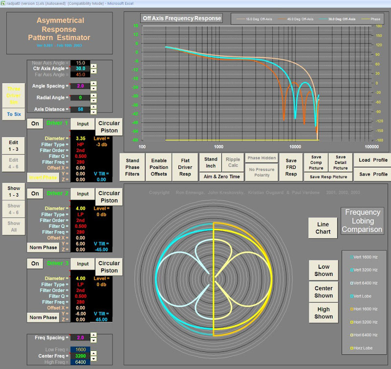
It can be done - sim desired driver in Enclosure Tool with box you wish to use, than go to next tab - Directivity and choose "Omni (ideal)". Uncheck box "Axial only" and you will see colorful graphs in Directivity (horizontal) window. This is poor approximation of direct loudspeaker radiator - piston directivity. No problem as we are using mainly Omni part of direct radiator directivity when dealing with directional arrays...
Now you are ready to export its Impedance and Directivity - there are appropriate buttons in Enclosure Tool.
Then, return to main program window and import Frequency responses as all *txt files assiociated with your driver name - it will visible right under left side. Import impedance as well if you like it. Then, play with x, y, z coordinates, position angles and timing and filters on each way - there are manyyyyyy possbilities, have fun.
Last edited:
Two videos how to create simulated off-axis responses for crossover designing. The first one is more complete: 2-way with crossover. These two are main options if off-axis measurements of final or compatible drivers are not yet available.
I hired Microsoft Zira Desktop for my spokeswoman or spokesrobot. She's quite okay for the job
Creating off-axis responses with Diffraction tool
Creating off-axis responses with Enclosure tool
I hired Microsoft Zira Desktop for my spokeswoman or spokesrobot. She's quite okay for the job
Creating off-axis responses with Diffraction tool
Creating off-axis responses with Enclosure tool
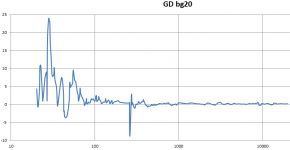
^GD result needs usually some smoothing because relation of phase and amplitude changes is not very accurate with interpolated or averaged and stepping response data. For example 1/3 oct. smoothing looks quite okay. Also main program has some smoothing and exception handling for irregular values, especially at the lowest octave.
Arta Recorder
Hi Kimmo,
I was looking over the built in function for ARTA to record off axis. Though I have not yet tried it, it seems to be that your effort is much more user friendly for a manual rotating table. I don't think that using it with the current version of ARTA is a problem but I was hoping that you might actively support it again.
Thanks for the consideration. Jay
^Jay,
I agree that all details in Record spatial IR group and Export spatial frequency response in ARTA are not as perfect and finalized for the user as they could be. Needed changes in ARTA are very small and easy, and integrated measurement and export functions are more reliable and faster than external remote controller such as Arta Recorder. Therefore I'd like keep Arta Recorder 6 feets under.
Details which need fixing in ARTA 1.9.0 in my opinion:
1) Settings in both windows should be saved for the next recording, exporting and sessions (to registry). Exceptions are settings in Export spatial.. which are picked from opened measurement: Start position, Gate length and Delay for phase correction.
2) Font size of Next angle: should be at least five times bigger that user could see the value at least few meters (Arta Recorder has 48pt).
3) "_deg" text should not be required in the filename because these features are serving also other applications and needs which do not require (or accept) "_deg" text. Value could be just a series of numbers 1,2,3,... separated with space from root filename. User can add "_deg" in the end of root filename if he's using for example Directivity pattern function in ARTA (while "_deg" requirement is not removed also from there).
Anyone is free to forward this list to Ivo Mateljan. As Clio 11 user I don't like to push any changes, though ARTA is only valid program for speaker measurements in this price category.
Last edited:
Just wanted to thank Kimmo for this incredible piece of software which I only stumbled across a couple of days ago - between this and XSim (and ARTA for measurement) I have tools at my disposal I wouldn't have dreamed of 10 years ago...
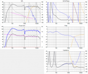
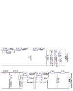
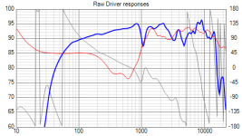
I've attached a couple of pics of the sims for the project I'm working on - a brand new crossover for a 2 way consisting of a Coral full range and an Aurum Cantus tweeter.
They have been kicking around in use for years with various crossovers and some digital EQ but I have never really put the effort into optimising the crossover properly as it was such a slow, tedious manual process for me without the right simulation software.
This time I wanted to include baffle step in the crossover, (I was previously taking the lazy way out doing it with digital EQ) use an all-pass to properly equalise the time delay of the two drivers which are not time aligned to achieve good phase tracking at the crossover, achieve a 24dB/oct Linkwitz/Riley accoustic response, and also deal with a couple of driver resonances.
I've literally only been working on the current design in VituixCAD for a couple of days not counting the time performing the measurements - it will be a complex crossover due to the quirks of the drivers and I could have kept it quite a bit simpler if I'd been less fussy, but I have to say I'm quite surprised at just how flat I was able to get the crossover region considering both drivers have a dip at 3Khz and the Coral's have a peak at 2Khz and 4Khz. It doesn't look nearly as pretty without the two notch filters...
It's not finalised yet and I'm undecided if I'm going to attempt to do anything about the surround dip at 1Khz in the crossover - it's always been there and while it looks nasty you don't really hear it, and it would be a fairly large cap and coil in an already complex crossover...
So getting on now to a wishlist and suggestions for the program because while it's extremely intuitive and powerful I did find a couple of odd bugs and do find a few aspects of the program a bit awkward to use. So things I noticed were:
1) I appreciate the "cookie cutter" circuit design that lets you combine blocks of common filter elements together, move them around, adjust them, toggle them in and out etc, but that can be a bit limiting in some ways, for example I can't find any way to add an RLC "notch" in parallel with my 5.6mH baffle step coil/resistor.
If I was to attempt to partially compensate the surround dip the only feasible way to do this would be to have a series tuned RLC bandpass which is then connected in parallel with the baffle step coil/resistor, but the circuit tools in this program do not allow such a configuration to be created, as far as I can see. I did simulate this manually in XSim which allows full free form circuit design to verify that it would work.
2) The "target response" overlay seems to have a mind of its own and keeps resetting back to defaults as I navigate and use the program. So every time I want to hand optimise the filter to match the target response I find myself having to reconfigure the target response.
3) It's unclear how the "target slope" (?) line is supposed to work - sometimes double clicking to zoom to full screen causes this line to move, sometimes you can grab an end and move it, sometimes it refuses to move. I guess it is there to measure an arbitrary slope but it seems very fiddly and uncooperative.
4) I find being unable to manually adjust the axes on most of the graphs very limiting. A good example is excess group delay. When I am looking at time alignment of drivers, or looking at the group delay introduced by an all pass section I need to be able to zoom the vertical scale so that the full graph height is about 1ms so I can see exactly what the excess group delay is - which is usually very small and less than 1ms over most of the frequency range. Trying to measure 0.1ms of excess group delay with a cursor when it is a single pixel on the screen is not possible.
In a program like ARTA its possible to measure very tiny amounts of excess group delay easily with the vertical axis adjusted, so please consider adding manual controls to all the graphs for axis scale and offset.
5) Overlays! The main graph windows really really need an overlay function, even if its just a single "hold" style overlay where you snap an overlay, then can make changes and see any changes relative to the saved version. This would make manual optimisation of crossover components vastly easier if you have a starting point available as an overlay.
Also being able to overlay two different "ways" on each other would be very helpful. In my project I have 4 "ways" configured, because my left and right drivers (especially coral drivers) differ enough that I must hand optimise the left and right crossovers to get the best response balance possible between the left/right speakers.
So Way 1 and 2 are woofer and tweeter for the left speaker and Way 3 and 4 are woofer and tweeter for the right speaker - each pair have the same crossover circuits but different component value optimisations, especially the notch filters. If there was a way to save and load overlays to files it would be possible to save one and overlay it on the other to make it easier to match them.
Perhaps an uncommon use case I know, but I find the overlays in ARTA very powerful and miss having anything like that here.
6) In group delay and phase response please consider adding an option to subtract the phase shift of two selected driver responses. When adjusting phase tracking through the crossover region for example adjusting an all pass filter its very difficult to see visually how well they track over a wide frequency range especially if the measurements have a lot of phase rotation in them. (delay for phase estimation was poorly chosen for the FRD export eg from ARTA for example)
Being able to subtract the phase of the two drivers whose overlap you are working on would make optimising phase tracking of the crossover region so much easier, as you are then trying to optimise a flat line along zero degrees.
7) I found myself using the invert and timing options in the drivers section a lot to confirm phase tracking of the crossover and perform a quick estimation of the vertical off axis response of the crossover by varying the timing offset (yes I know I don't have actual vertical off axis data for the drivers entered) however using the timing value without having up/down arrows to click on to quickly change it is quite tedious, also there is no tool tip or help to remind you whether a positive value moves the driver away or closer to the microphone, so I found I kept having to work out/remind myself which way the offset worked each time I used it. Having the option to adjust the delay directly in mm instead of us could be useful too.
That's about all I can think of at the moment - overall an incredibly easy to use and powerful program.
I've attached a couple of pics of the sims for the project I'm working on - a brand new crossover for a 2 way consisting of a Coral full range and an Aurum Cantus tweeter.
They have been kicking around in use for years with various crossovers and some digital EQ but I have never really put the effort into optimising the crossover properly as it was such a slow, tedious manual process for me without the right simulation software.
This time I wanted to include baffle step in the crossover, (I was previously taking the lazy way out doing it with digital EQ) use an all-pass to properly equalise the time delay of the two drivers which are not time aligned to achieve good phase tracking at the crossover, achieve a 24dB/oct Linkwitz/Riley accoustic response, and also deal with a couple of driver resonances.
I've literally only been working on the current design in VituixCAD for a couple of days not counting the time performing the measurements - it will be a complex crossover due to the quirks of the drivers and I could have kept it quite a bit simpler if I'd been less fussy, but I have to say I'm quite surprised at just how flat I was able to get the crossover region considering both drivers have a dip at 3Khz and the Coral's have a peak at 2Khz and 4Khz. It doesn't look nearly as pretty without the two notch filters...
It's not finalised yet and I'm undecided if I'm going to attempt to do anything about the surround dip at 1Khz in the crossover - it's always been there and while it looks nasty you don't really hear it, and it would be a fairly large cap and coil in an already complex crossover...
So getting on now to a wishlist and suggestions for the program because while it's extremely intuitive and powerful I did find a couple of odd bugs and do find a few aspects of the program a bit awkward to use. So things I noticed were:
1) I appreciate the "cookie cutter" circuit design that lets you combine blocks of common filter elements together, move them around, adjust them, toggle them in and out etc, but that can be a bit limiting in some ways, for example I can't find any way to add an RLC "notch" in parallel with my 5.6mH baffle step coil/resistor.
If I was to attempt to partially compensate the surround dip the only feasible way to do this would be to have a series tuned RLC bandpass which is then connected in parallel with the baffle step coil/resistor, but the circuit tools in this program do not allow such a configuration to be created, as far as I can see. I did simulate this manually in XSim which allows full free form circuit design to verify that it would work.
2) The "target response" overlay seems to have a mind of its own and keeps resetting back to defaults as I navigate and use the program. So every time I want to hand optimise the filter to match the target response I find myself having to reconfigure the target response.
3) It's unclear how the "target slope" (?) line is supposed to work - sometimes double clicking to zoom to full screen causes this line to move, sometimes you can grab an end and move it, sometimes it refuses to move. I guess it is there to measure an arbitrary slope but it seems very fiddly and uncooperative.
4) I find being unable to manually adjust the axes on most of the graphs very limiting. A good example is excess group delay. When I am looking at time alignment of drivers, or looking at the group delay introduced by an all pass section I need to be able to zoom the vertical scale so that the full graph height is about 1ms so I can see exactly what the excess group delay is - which is usually very small and less than 1ms over most of the frequency range. Trying to measure 0.1ms of excess group delay with a cursor when it is a single pixel on the screen is not possible.
In a program like ARTA its possible to measure very tiny amounts of excess group delay easily with the vertical axis adjusted, so please consider adding manual controls to all the graphs for axis scale and offset.
5) Overlays!
The main graph windows really really need an overlay function, even if its just a single "hold" style overlay where you snap an overlay, then can make changes and see any changes relative to the saved version. This would make manual optimisation of crossover components vastly easier if you have a starting point available as an overlay.Also being able to overlay two different "ways" on each other would be very helpful. In my project I have 4 "ways" configured, because my left and right drivers (especially coral drivers) differ enough that I must hand optimise the left and right crossovers to get the best response balance possible between the left/right speakers.
So Way 1 and 2 are woofer and tweeter for the left speaker and Way 3 and 4 are woofer and tweeter for the right speaker - each pair have the same crossover circuits but different component value optimisations, especially the notch filters. If there was a way to save and load overlays to files it would be possible to save one and overlay it on the other to make it easier to match them.
Perhaps an uncommon use case I know, but I find the overlays in ARTA very powerful and miss having anything like that here.
6) In group delay and phase response please consider adding an option to subtract the phase shift of two selected driver responses. When adjusting phase tracking through the crossover region for example adjusting an all pass filter its very difficult to see visually how well they track over a wide frequency range especially if the measurements have a lot of phase rotation in them. (delay for phase estimation was poorly chosen for the FRD export eg from ARTA for example)
Being able to subtract the phase of the two drivers whose overlap you are working on would make optimising phase tracking of the crossover region so much easier, as you are then trying to optimise a flat line along zero degrees.
7) I found myself using the invert and timing options in the drivers section a lot to confirm phase tracking of the crossover and perform a quick estimation of the vertical off axis response of the crossover by varying the timing offset (yes I know I don't have actual vertical off axis data for the drivers entered) however using the timing value without having up/down arrows to click on to quickly change it is quite tedious, also there is no tool tip or help to remind you whether a positive value moves the driver away or closer to the microphone, so I found I kept having to work out/remind myself which way the offset worked each time I used it. Having the option to adjust the delay directly in mm instead of us could be useful too.
That's about all I can think of at the moment - overall an incredibly easy to use and powerful program.
Attachments
Last edited:
DBMandrake, thanks for your feedback!
I have a plan to add few important blocks which are not yet available. (R+L+C)||(R+L) could be one of those.
Free schema won't happen in version 1.x. Probably never because it's so slow and mostly useless.
Correct. Settings are lost when window is closed with X button, and not saved to project file (vxp). This is known issue since day 0 but I always forget to improve it. Probably because I don't need target curves very often.
This should be found also in manual. Middle area is for zooming. Low and high frequencies are for setting ends of target slope.
I agree that span of group delay is sometimes too large, though zooming will show quite small changes in excess GD. I will add span to Options window. Span of other curves is adjustable.
Power&DI chart has overlay for all three curves. That is correct place to save intermediate result or any other reference for x/o tuning.
Very wide phase match (where level of acoustic signal drops below -40 dB) is quite or totally irrelevant. Phase matching is perfectly readable when timing of all drivers is adjusted equal, giving close to minimum phase with the tweeter. This is explained in Measurement preparations document.
See Measurement preparations document. No need to play with this at all if phase correction (e.g. PreDelay in ARTA) is applied while exporting frequency responses with measurement program.
Longer distance -> more delay should be quite logical. mm is visible just below microseconds.
1)..I can't find any way to add an RLC "notch" in parallel with ... coil
I have a plan to add few important blocks which are not yet available. (R+L+C)||(R+L) could be one of those.
Free schema won't happen in version 1.x. Probably never because it's so slow and mostly useless.
2) The "target response" overlay seems to have a mind of its own..
Correct. Settings are lost when window is closed with X button, and not saved to project file (vxp). This is known issue since day 0 but I always forget to improve it. Probably because I don't need target curves very often.
3) It's unclear how the "target slope" (?) line is supposed to work
This should be found also in manual. Middle area is for zooming. Low and high frequencies are for setting ends of target slope.
4) I find being unable to manually adjust the axes on most of the graphs very limiting.
I agree that span of group delay is sometimes too large, though zooming will show quite small changes in excess GD. I will add span to Options window. Span of other curves is adjustable.
5) Overlays
Power&DI chart has overlay for all three curves. That is correct place to save intermediate result or any other reference for x/o tuning.
6) consider adding an option to subtract the phase shift of two selected driver responses.
Very wide phase match (where level of acoustic signal drops below -40 dB) is quite or totally irrelevant. Phase matching is perfectly readable when timing of all drivers is adjusted equal, giving close to minimum phase with the tweeter. This is explained in Measurement preparations document.
7) I found myself using the invert and timing options in the drivers section...
See Measurement preparations document. No need to play with this at all if phase correction (e.g. PreDelay in ARTA) is applied while exporting frequency responses with measurement program.
Longer distance -> more delay should be quite logical. mm is visible just below microseconds.
Great to hear.I have a plan to add few important blocks which are not yet available. (R+L+C)||(R+L) could be one of those.
Free schema won't happen in version 1.x. Probably never because it's so slow and mostly useless.
I'm not suggesting full freeform schematic design (like XSim) is needed, it's just that was one case where I found I couldn't create the desired design with the blocks available.Perhaps you could add an option to vertically stack or otherwise combine existing series blocks ?
At the moment it's already possible to horizontally stack and combine vertical blocks (as I did with my two shunt notch filters) but not horizontally when they are in series. Being able to combine them would be a more general solution than just adding one more specific block type.
Not sure how this would be visualised in the interface though.
I assumed that the target responses would be lost when the program is closed, but that's not what I mean - I also have them frequently being lost and reverting to defaults even when I don't close the program or save the file.Correct. Settings are lost when window is closed with X button, and not saved to project file (vxp). This is known issue since day 0 but I always forget to improve it. Probably because I don't need target curves very often.
This seems to be semi-random. I tried to reproduce it just now and was able to once but couldn't repeat it. When it happened I had only way 1 and 2 ticked in the drivers tab, I then performed some other actions then when I came back I found the target response for ways 3 and 4 had reverted to defaults while ways 1 and 2 were retained.
So it seems that target responses are lost for ways that are unticked when certain actions are performed. I'll keep trying to isolate exactly what actions triggered this. It was certainly happening to me a lot during the design process as I was jumping between left (way 1/2) and right (way 3/4) a lot while optimising left and right designs to try to get them to match closely - I must have reset the target responses about 20 times in half an hour.
I see now what the problem is - the line seems to have a minimum length after which it stops responding to the mouse. So say I start with the left end near the top left corner and grab the right end and drag down to the left once I go past a certain point it will "stick" and not let me make the line any steeper as it results in the line being too short, however if I go down towards the right to form a longer line it will let me make it steeper.This should be found also in manual. Middle area is for zooming. Low and high frequencies are for setting ends of target slope.
Does that make sense ? This odd restriction in the line length is a bit counter intuitive and makes it difficult to create a steep line in some locations on the graph.
Thanks - adjustable span for group delay and excess group delay would be excellent. Excess group delay in particular can be very small on the order of 0.1ms but is useful to identify acoustic centre offset between drivers and whether the crossover is correcting for this or not.I agree that span of group delay is sometimes too large, though zooming will show quite small changes in excess GD. I will add span to Options window. Span of other curves is adjustable.
Thanks - I didn't realise this and must have missed it in the manual. (I haven't read the whole manual cover to cover - the program is so easy to use that I just jumped in and started using it and didn't refer to the manual a lot, just for a few things I wasn't sure about)Power&DI chart has overlay for all three curves. That is correct place to save intermediate result or any other reference for x/o tuning.
In my defense, because I only have on axis measurements and am not taking advantage of the Power response and DI calculations I had not looked closely at the Power & DI graph to see that it had overlay functions that other graphs did not.
One issue though is that the colours can't be customised (?) so I am looking at a thick blue line overlaid on top of a thin blue line on a white background... Not the easiest to see when I'm used to the black background and highly contrasting colours like red and blue on ARTA. (ARTA really does have excellent customisable overlay functionality!)
It's a pity the other graphs are lacking overlay functionality, (including phase) and ideally they would all have it, but the overlay feature on the Power & DI graph will do what I need for basic overlay functionality including comparing different ways as well as prior versions of the same way when optimising. I wish I'd discovered this earlier.
I'm not sure I agree with this.Very wide phase match (where level of acoustic signal drops below -40 dB) is quite or totally irrelevant. Phase matching is perfectly readable when timing of all drivers is adjusted equal, giving close to minimum phase with the tweeter. This is explained in Measurement preparations document.
See Measurement preparations document. No need to play with this at all if phase correction (e.g. PreDelay in ARTA) is applied while exporting frequency responses with measurement program.
In my driver measurements the phase response of the tweeter was already unrolled correctly in ARTA by using "delay for phase estimation" and adjusting this until the excess group delay in the tweeters passband was exactly zero. (A good example of a use for a very detailed scale for excess group delay.
)This gives the minimum possible phase rotation for this driver's measurement. I then measured the midbass driver from the exact same equidistant microphone position, and both measurements were taken in dual channel mode and with the same value of "delay for phase estimation" to ensure exact timing and precise phase relationship between the two separate driver measurements.
Because the midbass driver's acoustic centre is some distance behind the tweeter this means the phase response for this driver will have a lot of phase rotation - but I cannot reduce the phase rotations or the phase relationship with the tweeter will be lost.
When I then simulate these drivers in VituixCAD I have the phase rotations of the midbass driver to deal with, and when I add the all pass filters to the tweeter to achieve phase tracking now the tweeters have the same phase rotations, which become difficult to look at on a raw phase graph - hence why I was suggesting a phase difference mode.
Phase difference would also be useful for adjusting cascaded all pass filters for best linear phase response over the widest range possible, as it is much easier to judge a horizontal line against a grid than a steep sloping line.
The box is labelled "Timing" not delay, so it's not obvious that a positive number means more delay. If it was called delay it might be more obvious. It's a minor quibble but I did find myself forgetting which way around it was. Yes, mm is displayed below the delay figure, but its more useful to be able to specify a distance directly rather than keep trying approximate delay values to find the distance you are looking for. Acoustic centre offset of drivers is normally represented as a distance rather than a time delay.Longer distance -> more delay should be quite logical. mm is visible just below microseconds.
Last edited:
I also have them frequently being lost and reverting to defaults even when I don't close the program or save the file.
I meant closing small SPL Target window with X button (not whole program). Closing with Close button hides the window, but settings wont reset.
Anyway, way target issue is already fixed few minutes ago and will be much better in the next revision 1.1.13.0. Targets are also saved to project file (vxp) for the next session.
Aha, I think that's what I may have been noticing!I meant closing small SPL Target window with X button (not whole program). Closing with Close button hides the window, but settings wont reset.
As a test I set target responses on Ways 1-4 and made sure to always click apply and then close, and when I switch ways the targets are correctly retained, however when I go into the SPL target dialog even if I click X without changing anything, although the target doesn't immediately change on screen all previously configured target's are lost which can be seen when switching ways where they will be seen to have gone back to defaults.
Sounds great!Anyway, way target issue is already fixed few minutes ago and will be much better in the next revision 1.1.13.0. Targets are also saved to project file (vxp) for the next session.
- Home
- Design & Build
- Software Tools
- VituixCAD