^It's distance from baffle surface point 0,0,0 to mic or ear in the simulation. No effect if your project is single coaxial or full range or very compact multi-way. Relative distance from non-centered drivers to listening point will increase at short listening distance. That increases phase difference and attenuation and non-symmetry to directivity while rotating in vertical plane.
^It's distance from baffle surface point 0,0,0 to mic or ear in the simulation. No effect if your project is single coaxial or full range or very compact multi-way. Relative distance from non-centered drivers to listening point will increase at short listening distance. That increases phase difference and attenuation and non-symmetry to directivity while rotating in vertical plane.
Kimmo, thank you, I understand. I did not notice choosing the speaker coordinates. My mistake. Sorry.
Hi Kimmo,
Your software just keeps getting better and better. I had a few thoughts to consider. Here are my thoughts:
1. the ability to map a wider frequency range (at least to 24K and perhaps to 48k for those who believe it matters).
2. an option for export of frd files without the first few lines of comment as one has to edit out the first few lines for it to be imported into Passive Crossover Designer and Windows PCD; I know that for myself, my company won't allow your program to run so occasionally on down time I will mess around with Jeff's PCD there.
3. An option to Undo when designing crossovers.
4. the ability to extend the dB range
5. The ability to import distortion measurements (not sure that this is feasible as it seems like it is saved in various ways or not saved at all in different software)
6. Allowing for a user defined range of blending rather than octave based
7. Rather than estimating Minimum Phase based upon the upper and lower half octaves, perhaps allowing the user to set HP and LP slopes and frequency ranges prior to MP extraction.
Please do not misconstrue my comments in any way. I am very appreciative of all of your efforts and the wonderful software.
Thanks again,
Jay
I am very appreciative of all of your efforts and the wonderful software.
Thanks Jay!
1. 24k is not much higher than existing 22k. 48k would lead to forced extrapolation and possible errors or other bad behavior with most of the users. 48k was available in early versions but removed for several good reasons. Better that data is actual measured also with the lowest (44.1k) sample rate, and range is valuable for speaker engineering.
2. I've totally forgot to skip header line with .frd and .zma exports (because this works with or without headers). I can also add boss key for opening dummy Excel screenshot or PCD.
3. Undo would be nice but quite difficult to implement.
4. Existing max. of 60 dB is quite much for crossover tuning. Calculator can be used for publishing flat responses from bad drivers or speakers
")
5. This would need guessing how distortion changes by frequency and SPL, or quite many measurements and some interpolation. I test minimum/maximum crossover frequency with DSP HP/LP filter if some restrictions are expected.
6. Setting of both ends would be slower because blending range is quite irrelevant. 1 oct. works fine when merging near and far field measurements. 2-3 octs. is fine when merging simulated box+driver+directivity and measured far field. Range limits are shown by the cursor.
7. Response file can be manipulated with text editor before MP calculation if user thinks he "knows" missing bands better than automatic slope detection. Instant MP calculation such as for excess group delay and piston directivity is much more valuable for me than (slow) manual slope setting with assumed accuracy. Small phase error at HF can be compensated with timing (us).
Thanks Kimmo for your consideration of my suggestions.
I am not certain why the blending range is irrelevant as the dependability of measurements varies depending upon which measurements they are and what the frequency is. Setting one's own slopes is of advantage when one knows the noise floor (at what point to minimize the importance of the measurements) and also for HP tails. I see the point in your other answers and I see that there is always a balance between flexibility and speed and usefulness.
Thanks again,
Jay
...why the blending range is irrelevant as the dependability of measurements varies depending upon which measurements they are and what the frequency is.
Of course it's not totally irrelevant because sharp 0 oct. blending would force to select splicing frequency producing exactly 0.0 dB step with given LF scaling. 1 oct. range gives small but adequate freedom to select frequency producing a bit smoother transition.
Wider than 1 oct. range is not needed for near+far merging. It could be bad thing if level and resolution drop (due to time windowing) of HF response is close to frequency where cone area/directivity drops amplitude of LF near field measurement. Possible blending range could be quite narrow in practice. For example this 15" coaxial woofer could be merged with sharp 0 oct. blending because range having common amplitude is only about 1 oct.

1 oct. range produces nice merging to 0-180 deg - as expected.

Anyway, Merger tool could have two frequency cursors: left cursor for range and right cursor for frequency. Left cursor would move along with right cursor. That would not make using more difficult and slow.
export of frd files without the first few lines
This is done in revision 1.1.10.5. Both .frd and .zma files are exported without header line. Applies to all FR and ZR exports in main program and tools. Exception is LspCAD 6 extended data format @Merger which is .txt only.
Improved also phase matching (LF delay calculation while transition freq. adjustment) and phase blending in Merger tool. There were occasional mistakes or bad logic in phase response matching and blending.
I mean range of angle, when I have only 90 degrees, the information is only displayed in half the graph.^If you mean span or range of angle axis, that is constant -180...+180 deg. All measured angles which are common for enabled ways are visible.
I mean range of angle, when I have only 90 degrees, the information is only displayed in half the graph.
Hopefully that ugliness encourages to measure full 0..180 deg
Tilt of power response and DI are not correct without full 0-180 data in both planes, though shape is probably quite okay with box speakers. Requirement applies also to dipole due to front-back asymmetry in practice.Passive crossover capability is too limited.
It would be useful to define your own library of blocks.
It would be useful to define your own library of blocks.
An externally hosted image should be here but it was not working when we last tested it.
Thanks guys! Hopefully I can keep this software alive and add some new features in the future, though new ideas and motivation are slowly decreasing. Maybe because it's already so perfect
-Kimmo
Hi Kimmo
Have you considered a Patreon account where you make videos of every stage of creating a good speaker. YouTube has started to gain a few in recent years but they really don't start at the beginning, leave lots out etc. I would certainly support that, especially if you created videos answering questions, and created a few budget projects everyone could follow with. i.e. Dayton or Perless speakers etc.
As an example i have some very high quality drivers but that are proprietary so no published specs exists. I have tried to google the process and i know i need to measure TS parameters with say Arta, then build a box and measure frequency response, then i assume try to find a tweeter which would cross well with the driver etc..... However, no one actually provides this information clearly. Just an idea
...make videos of every stage of creating a good speaker...
I have often thought about that, and tested some screen capturing tools for creating video lessons. But I think that someone native English would be much enjoyable to listen
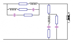
How to make such a circuit for example?
Particular circuit should not the goal. It's transfer function producing excellent combination of axial, off-axis, power and impedance responses including well-behaving directivity index. Target is so large combination that too tight tolerance for example in axial response only, and requirement of particular circuit probably will not pay back.
You can propose max. four new fixed blocks if you are confident that those are really needed for transfer function which is not possible with existing blocks within reasonable tolerance. Create full speaker project with complete off-axis response set and power&DI and impedance simulation to show that block requirement is valid.
You can propose max. four new fixed blocks if you are confident that those are really needed for transfer function which is not possible with existing blocks within reasonable tolerance. Create full speaker project with complete off-axis response set and power&DI and impedance simulation to show that block requirement is valid.
1. The accurate impedance compensation for a (mid)woofer in closed box or a tweeter.
2 - 4 later
Attachments
1. The accurate impedance compensation for a (mid)woofer in closed box or a tweeter.
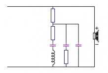
That is not really needed in real life projects. Flat impedance curve inside some crossover network is not the final target. It's acoustical responses of individual drivers/ways and whole speaker. If you need adequate impedance compensation, that can be done with parallel R+L+C and R+C. It's not perfect but certainly enough to get required acoustical responses.
Z-response of many compression drivers is much more complicate than basic cone driver. Network you proposed won't be accurate anymore, but multiple R+L+C in parallel could work much better.
Quite flat total impedance response is worth in some cases, for example with tube amps. Original curve is usually not equal to Z-response of single closed/free electrodynamic driver. That can be compensated with parallel blocks before low and high pass filters.
- Home
- Design & Build
- Software Tools
- VituixCAD