A big problem with putting anything conductive on a sheet of plastic (regardless of the plastic) is *heat*. Most adhesives give up quickly with heat. Given that most speakers of any type are under 1% efficient, that means that you have to radiate or conduct away 99% of the power as heat.
The other half of the "ribbon" equation (planar or pure metal ribbon) as was previously noted is mass vs. conductivity. Copper is killed by mass for HF applications. But the mass of the adhesive is part of this equation is important and not to be ignored. I guess for midrange and bass it may not make much of a difference.
But I do like the idea of etching based on a resist.
Why not use a standard photoresist for PCBs??
_-_-
Few
I made something like you do:http://www.diyaudio.com/forums/planars-exotics/218549-diy-amt-37.html#post3678607
It is used for AMT´s, but it is the same material ,and etching teknique .
I still have some 7my alu/15my mylar. PM me for sending you some meters 180mm wide.
Bernt
I made something like you do:http://www.diyaudio.com/forums/planars-exotics/218549-diy-amt-37.html#post3678607
It is used for AMT´s, but it is the same material ,and etching teknique .
I still have some 7my alu/15my mylar. PM me for sending you some meters 180mm wide.
Bernt
It is from China.
It is almost imposibly to get smal quantityes .
Try this one:AL/PET TAPE (ALUMINUM MYLAR TAPE)
Bernt
It is almost imposibly to get smal quantityes .
Try this one:AL/PET TAPE (ALUMINUM MYLAR TAPE)
Bernt
Ortho headphones foil repair
I would like to duplicate the diaphragm of my broken orthodynamic headhones, as seen here:
Technics EAH-830
I bought a roll of food wrapping foil, that has an aluminium layer on PVC (the material I am not sure of). How can I transfer the pattern from the intact diaphragm to the foil? It has a very dense pattern, so photocopying seems the only way to go.
Thanks, all, for your interest. I discovered that a small region of the screen I made did not get properly cleared of emulsion. I tried it anyway just to gain a little screen printing practice. As expected, the area of the screen that was supposed to be clear but which was partially blocked did not print properly.
Lesson learned: examine the screen VERY carefully while rinsing away the emulsion that was not exposed to UV light to be sure the job is done thoroughly. Once the screen is exposed to the second blast of UV it will be impossible to remove emulsion that's left where it shouldn't be.
I was also left wondering whether my 0.5 mm gaps between conductors are just a little too narrow to be screen printed reliably over a large area. I need to make about 16 useable diaphragms and it will be frustrating if I need to print 3 in order to create each usable one.
I therefore drew up another pattern using 0.75 mm gaps. I created a screen from the transparency and rinsed it more carefully! The new gap seems wide enough to reproduce reliably but it makes the conductor pattern wider. That, in turn, requires a wider separation between magnets. A little too wide, I think (based on my FEMM simulations and examining the magnet systems of commercial planar magnetics). I will try retaining the 0.75 mm conductor gaps but running 3 instead of 4 conductors in each magnetic gap. I hate to give up the extra length of conductor but if I have to kill the magnet field strength to use it I won't be getting anywhere.
When screen printing my 4 conductor, 0.75 mm pattern I discovered a problem with one of my "brilliant" ideas. I had taped down one edge of the transparency so I could more easily position the photosensitive screen under it while working in dim light. I think the tape prevented the glass cover from properly pressing the taped edge of the transparency to the photosensitive screen. I saw evidence that some UV light snuck under the black traces of my transparency and created poorly defined edges on the pattern in the emulsion. That left me with narrow spots in the resist pattern and narrowed aluminum conductors near to the taped edge.
Another lesson learned: be sure the transparency is pressed firmly to the photosensitive screen at ALL points before doing the UV exposure step.
This must be a real project because every time I improve something I learn something else is a problem!
Bear: Others report success using 3M 77 spray adhesive for this purpose so for now I'm going to assume the adhesive's thermal limits won't be a problem. Time will tell, I guess. On the weight issue, the Infinity white paper on their EMIM and EMIT drivers showed that they used thicker sandwiches for their diaphragms than I'm using and their EMIT worked out to 45 kHz. I'm using a single sided magnet system so I expect weaker fields, but I'm hopeful that I'll get decent response out to 15 kHz or above. Again, time will tell. That's why these are prototypes!
Bernt: Thanks very much. I have sent you a PM.
Few
I bought a roll of food wrapping foil, that has an aluminium layer on PVC (the material I am not sure of). How can I transfer the pattern from the intact diaphragm to the foil? It has a very dense pattern, so photocopying seems the only way to go.
If you are considering screen printing I think you will have to do more than photocopy. You need very dense very consistent blacks on your transparency if you want to use it to create a screen for screen printing. Maybe you can photograph, or even better scan, the original pattern to create a digital file. You could then clean up the image and make sure all the blacks are fully dense with no pinholes before printing the transparency.
Few
I sooort of did this with a Technics EAH-820, although because of the dense pattern and my capabilities I just blurred lines together, more or less.I would like to duplicate the diaphragm of my broken orthodynamic headhones, as seen here:
Technics EAH-830
I bought a roll of food wrapping foil, that has an aluminium layer on PVC (the material I am not sure of). How can I transfer the pattern from the intact diaphragm to the foil? It has a very dense pattern, so photocopying seems the only way to go.

As you can see, I'm not nearly as proficient as Few in the exposing/developing/etching processes. I used a scanned image of the 820 circuit layout and a photo editing piece of software called Gimp to create the transparency image, iirc, although I may have come to the realization that it was easier for me to just get a ruler out, take some measurements, and get to work in MS Paint. Why are you interested in repairing the 830? Sentimentality, or?
Currently looking into the viability of using a Peachy Printer to expose our artwork into our raw, sensitized diaphragms. Stop by the 3D printing thread over on Head-Fi, if you don't mind.
Last edited:
Well I'm still trying to get my proficiency up to the level necessary to make this work so we're all in the same club.
I've printed up a transparency for a three conductor per gap pattern and will try to create a silk screen from it this afternoon. I hope to avoid some of the mistakes I've made in the past; time will tell whether I'm successful.
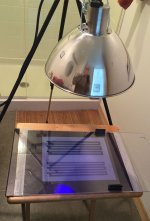
I thought I'd post a couple photos of my simple UV exposure set-up on the off chance someone would find them useful. The key point is finding a cover that will press the transparency firmly to the photosensitive emulsion on the silk screen and that will also transmit enough UV light. The first photo shows the lamp mounted above my glass-covered exposure platform. A reflection of the purple glow from the UV compact fluorescent bulb is visible in the glass cover. I keep the lamp about 12 inches above the transparency as a decent compromise. If it's closer the exposure takes less time but it is less even across the emulsion (my patterns are about 9 inches by 4 inches). Also, a point source of light gives sharper edged exposures, meaning more distinct edges on the resulting aluminum conductors, than does a broad diffuse source of UV. Moving the lamp farther away and using a single bulb makes it act more like a point source. Lately I've been using about 1.5 minutes of exposure with the bulb about 12" above a thin glass cover. (Apologies to readers who are not in the USA, Liberia or Myanmar; I keep switching between metric and stupid-units.)
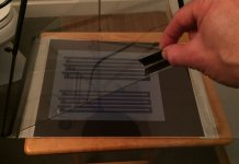
The second photo shows how the glass lid is hinged at one edge so it's easier to handle things in the dark. Try to ignore the porcelain fixture in the background of my photo lab. This bathroom is about the only room in my house that doesn't have windows so I'm using it as my dark room.
I've printed up a transparency for a three conductor per gap pattern and will try to create a silk screen from it this afternoon. I hope to avoid some of the mistakes I've made in the past; time will tell whether I'm successful.
I thought I'd post a couple photos of my simple UV exposure set-up on the off chance someone would find them useful. The key point is finding a cover that will press the transparency firmly to the photosensitive emulsion on the silk screen and that will also transmit enough UV light. The first photo shows the lamp mounted above my glass-covered exposure platform. A reflection of the purple glow from the UV compact fluorescent bulb is visible in the glass cover. I keep the lamp about 12 inches above the transparency as a decent compromise. If it's closer the exposure takes less time but it is less even across the emulsion (my patterns are about 9 inches by 4 inches). Also, a point source of light gives sharper edged exposures, meaning more distinct edges on the resulting aluminum conductors, than does a broad diffuse source of UV. Moving the lamp farther away and using a single bulb makes it act more like a point source. Lately I've been using about 1.5 minutes of exposure with the bulb about 12" above a thin glass cover. (Apologies to readers who are not in the USA, Liberia or Myanmar; I keep switching between metric and stupid-units.)
The second photo shows how the glass lid is hinged at one edge so it's easier to handle things in the dark. Try to ignore the porcelain fixture in the background of my photo lab. This bathroom is about the only room in my house that doesn't have windows so I'm using it as my dark room.
Attachments
The exposure process is complete and it seems to have gone well. I'll need to do a print to know for sure, but I don't see the telltale regions of emulsion residue where it should have been removed so I'm optimistic. I also don't see the variation in trace width that I saw on my previous try so I think eliminating the tape I mentioned in a previous post helped keep the transparency firmly pressed against the emulsion. I also moved the lamp a bit farther away and exposed for 1 min 50 sec to try to get more uniform exposure.
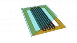
The attached Sketchup drawing shows what I'll try for my first prototype once I print and etch a conductor pattern. The diaphragm is cut away in one corner to make it a little easier to see the columns of 1" x 0.25" x 0.125" NdFeB magnets.
The wide gaps at the sides are there so that I can experiment with methods of damping the undriven parts of the diaphragm. Some discussions in the context of diy ESL speaker design suggested that the treatment of the diaphragm/frame interface combined with the diaphragm tension determine how much hash will appear in a waterfall plot (thanks again Capaciti). I'm going to try to apply those ideas to these drivers.
Few
Attachments
Great Stuff, Few !!!
Keep going!!
Have you done any etching yet?
If so what are you using to etch with if you are using Aluminium?
I have been wanting to try this for years, But I never invested in the initial cost of the materials.
The one question I have is that once make a silkscreen isn't it permanent or can the screen be cleaned and be reused?
Thanks!!
jer
Thanks for your interest and enthusiasm Jer. I'm not sure it's justified, but it's appreciated nonetheless!
I'm half way, maybe three quarters of the way, to finishing the etching. I did a print, meaning I glued some Al foil to some 6 um mylar and screen printed the acrylic paint through my latest screen to form the resist pattern. The results were better than with my last attempt. The traces have consistent width and no gaps. The refinements I made seem to have helped. I say I'm three-quarters of the way there because the screen printing step is much touchier than the etching. If the resist goes down well you just have to avoid falling asleep while the etching takes place. It's pretty forgiving.
I haven't done the etching yet because I need to wait a bit for the acrylic paint to dry so that it doesn't dissolve in the aqueous solution of ferric chloride that I'm using for etching. There seems to be an ideal drying time for the acrylic. I have to wait long enough for the acrylic to dry sufficiently to survive the etching process, but it gets increasingly difficult to remove the paint from the traces the longer it sits on them. I've waited more than 24 hours and have still been able to remove the acrylic without major problems, so it's not a super-narrow time window. It's just extra easy to remove the acrylic if you can do it during the sweet spot.
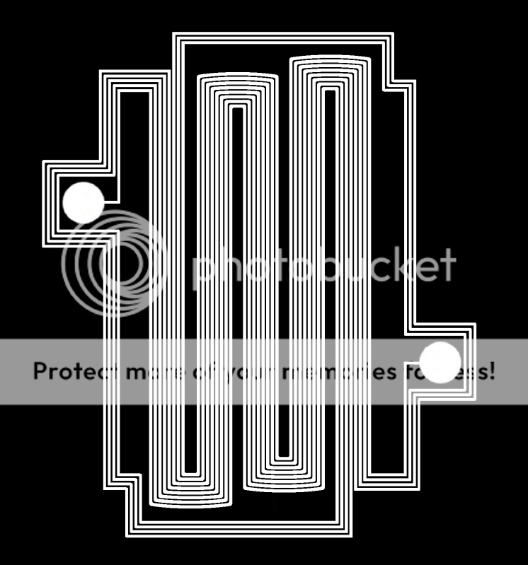
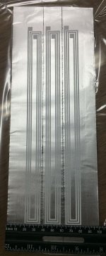
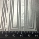
I wish I had the final images of the etched conductors to share, but I don't want to try it now that I've had a celebratory martini. Etching and martinis seem like a bad combo. I've attached a few images to convey where things stand at the moment. The first two show the white acrylic paint (which serves as an etch resist) on the aluminum which is, in turn, glued to mylar. The first shows the whole pattern, the second shows a close-up. The patterns seems pretty good down to about the 0.1 mm scale which is good enough for me. My favorite local and non-local expressions for that sentiment are:
1) "Close enough for government work."
2) "Good enough for a barn; it'll never be a church." (This needs to read with a Maine accent to be fully appreciated.)
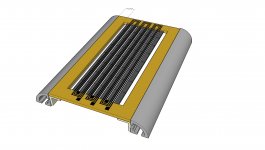
The third photo shows my latest thinking about how all this might come together. I'm exploring the option of using 80/20 aluminum extrusions to frame the drivers if and when I actually get them working. The third image shows one version of what that might look like if I use 1 inch by 1 inch rounded extrusion for the 2 vertical frame pieces, and 0.75" angle aluminum to attach the drivers to the extrusions. I tried to switch to mm for the photos of the screen printing and now I'm back to inches. Sorry about that.
I'm half way, maybe three quarters of the way, to finishing the etching. I did a print, meaning I glued some Al foil to some 6 um mylar and screen printed the acrylic paint through my latest screen to form the resist pattern. The results were better than with my last attempt. The traces have consistent width and no gaps. The refinements I made seem to have helped. I say I'm three-quarters of the way there because the screen printing step is much touchier than the etching. If the resist goes down well you just have to avoid falling asleep while the etching takes place. It's pretty forgiving.
I haven't done the etching yet because I need to wait a bit for the acrylic paint to dry so that it doesn't dissolve in the aqueous solution of ferric chloride that I'm using for etching. There seems to be an ideal drying time for the acrylic. I have to wait long enough for the acrylic to dry sufficiently to survive the etching process, but it gets increasingly difficult to remove the paint from the traces the longer it sits on them. I've waited more than 24 hours and have still been able to remove the acrylic without major problems, so it's not a super-narrow time window. It's just extra easy to remove the acrylic if you can do it during the sweet spot.
I wish I had the final images of the etched conductors to share, but I don't want to try it now that I've had a celebratory martini. Etching and martinis seem like a bad combo. I've attached a few images to convey where things stand at the moment. The first two show the white acrylic paint (which serves as an etch resist) on the aluminum which is, in turn, glued to mylar. The first shows the whole pattern, the second shows a close-up. The patterns seems pretty good down to about the 0.1 mm scale which is good enough for me. My favorite local and non-local expressions for that sentiment are:
1) "Close enough for government work."
2) "Good enough for a barn; it'll never be a church." (This needs to read with a Maine accent to be fully appreciated.)
The third photo shows my latest thinking about how all this might come together. I'm exploring the option of using 80/20 aluminum extrusions to frame the drivers if and when I actually get them working. The third image shows one version of what that might look like if I use 1 inch by 1 inch rounded extrusion for the 2 vertical frame pieces, and 0.75" angle aluminum to attach the drivers to the extrusions. I tried to switch to mm for the photos of the screen printing and now I'm back to inches. Sorry about that.
Attachments
![URL]](/community/proxy.php?image=http%3A%2F%2F%5BURL%3Dhttps%3A%2F%2Fimageshack.com%2Fi%2Fnb5a0tj%5D%5BIMGDEAD%5Dhttp%3A%2F%2Fimagizer.imageshack.us%2Fv2%2F1024x768q90%2F839%2F5a0t.jpg%5B%2FIMGDEAD%5D%5B%2FURL%5D&hash=4e04c5423defb09b9807459c38a078a0)
It looks like your cutter does a nice job! Is the foil attached to a substrate when you cut it? How small a gap between conductors can you create reliably?
My next two days will be very busy but I will post a dimensioned drawing as soon as things settle down. Thanks for the offer. What file formats does the cutter work with? If I can export the artwork in the right format I could save you some effort.
Few
My next two days will be very busy but I will post a dimensioned drawing as soon as things settle down. Thanks for the offer. What file formats does the cutter work with? If I can export the artwork in the right format I could save you some effort.
Few
I see. Is it easy to transfer the cut foil to your diaphragm and remove it from the cutting mat? Could you create narrower gaps if you wanted to? The price seems quite reasonable. I see that it could be used to cut ribbons over 3 meters long. That would be quite a line source!
Jer,
I just realized I didn't answer one of your questions. Sorry for the omission.
The screens are permanent once the pattern is transferred to them. Traditional screen printing techniques would allow you to reuse the screen but the initial investment would be higher. The screens I'm using are ideal for my purposes, plus the photo emulsion is perfectly applied every time (my impression is that applying the photoemulsion to a conventional screen isn't trivial). I'm sure the traditional approach is better for many applications. The precoated screens have been great or me so far, though.
Few
Note that the Silhouette Cameo is 12 inches wide, Portrait is 8. But that at almost a double price.I see. Is it easy to transfer the cut foil to your diaphragm and remove it from the cutting mat? Could you create narrower gaps if you wanted to? The price seems quite reasonable. I see that it could be used to cut ribbons over 3 meters long. That would be quite a line source!
But in this context it is still really cheap as it saves you so many process steps.
Also, the longest cutting mat is 12x24, so you would have to make your own cutting mat if you want longer ribbons.
You can look at these posts in my thread (Yet another DIY AMT) if you want to some more pictures.
- Status
- This old topic is closed. If you want to reopen this topic, contact a moderator using the "Report Post" button.
- Home
- Loudspeakers
- Planars & Exotics
- Viability test: DIY screen printing for planar magnetics