Asymmetrical clipping
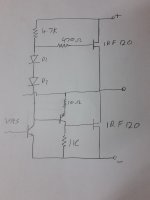
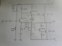
O.K. I have attached two hand drawn ccts. (rough). What I meant is that the output devices are the same. no mix of mosfet and BJT and the VAS cct is at opposite ends of the rails. I do not want to mix outputs and want to keep it very simple. These both scenarios have the same clipping problem but at opposite ends. One clips negative first and the other clips the positive first. but if you use BJT outputs the clipping is the same in both. Clipping asymmetrically is not a real problem although you have significantly less output power with the same supply rails as with BJTs. I like the CCTs you have produced here but they are not simple enough to claim them simple. I don't have resources to PCBs. I make everthing on vero board.
Regards.
Billy D...
Attachments
Bill,
Your suggestion is that the adjective 'simple' is not correct? Is that it?
Yes, to some degree I agree it is not that simple, BUT, it works well, gives excellent headroom and uses very few additional parts; notably the Baxandall network which is often seen with quasis. A few builders here said that this was one of the best amps they'd ever built/heard, so the aim was meet. Certainly it's very melifluous, sweet and reliable. This relates to its harmonic profile; THD is quite high, around 0.05%.
In truth, you could probably drop the Baxandall network because there can be no equivalent mosfet drive with bjt drive; but it was added to make setting the quiescent a little less tetchy, which is significant with many PP amps.
HD
Last edited:
I don't have resources to PCBs. I make everthing on vero board.
Billbo,
Do you have access to a laser printer? Have some Sharpie markers or a graphics program like PowerPoint? A clothes iron, some muriatic acid (sidewalk cleaner from hardware store), some hydrogen peroxide from drugstore? Cheap copper clad blank PCB's from China? For about $10 worth of supplies not including laser printer, you can etch your own PCBs at home. I make my layouts on PowerPoint, then iron transfer to copper and etch in 3:1 acid to peroxide. Works very well and fast and cheap. For real simple circuits I hand draw the traces with a Sharpie as the resist.
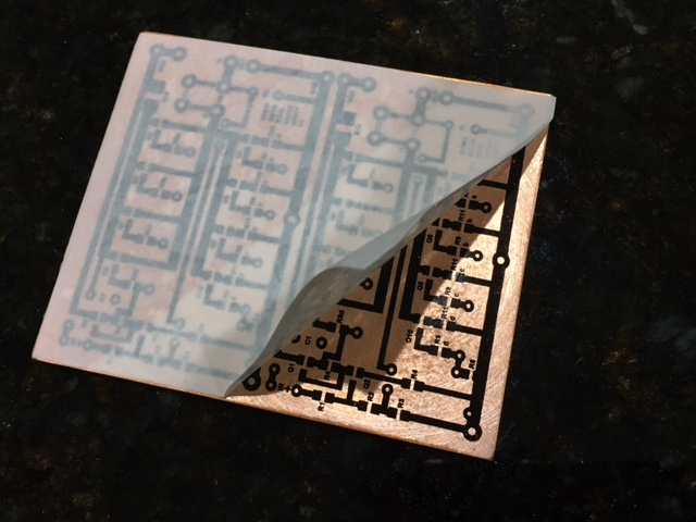
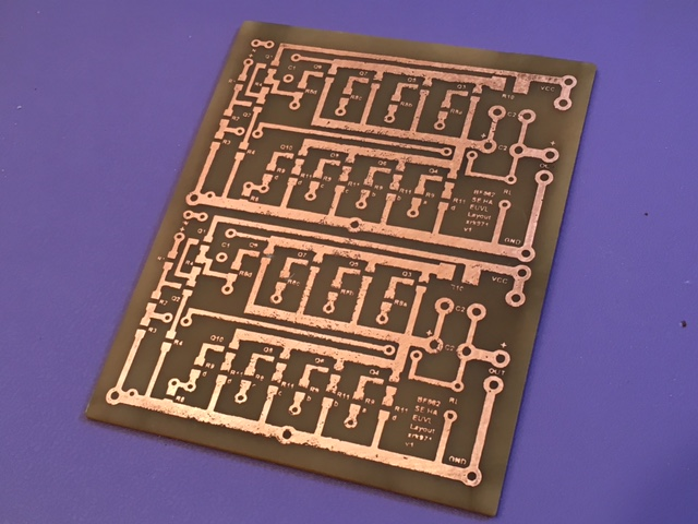
I have actually built a variant of the Ranchu-Aksa Quasi as a headphone amp this way - the HyQu:
If I like what I hear at this stage then a real layout is made and boards ordered from overseas by a robot-staffed factory for peanuts.
")
Last edited:
All good stuff here!
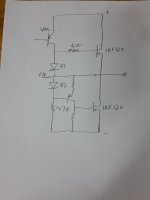
I have done some tests on a cct. that I have (keep in mind I am only working with what I have in my junk box) and I found out that the quasi setup with a current feedback arrangement using a single input transistor and feedback into its emitter leg does not pose any clipping problems at all. Thus total component count would be reduced. Saying this, diff input phase problems (if it is a problem) is not a concern with this topology but hum and noise may be a problem. This can be fixed in power supply arrangement. Just a thought in case someone wants to build something very simple. P.S. cct attached for explanation. Rough sketch out of my head.
Regards.
billy D...
Attachments
You can use a 4 transistor bootstrap output or 5 transistor constant current version of this with n and p mosfets and 5.6v bias zener with better results.
adding another 5401 for differential input makes biasing far simpler
All true, but this is not actually the aim. A LTP is conventional and works very well, and was considered...... like the CCS in place of the bootstrap. But these conventional approaches were found wanting, so we looked elsewhere to create a better sound.
The idea is to create an amp with sound quality is exceptional. If you build a conventional design, it will sound like just the others in the market. We wanted to do something different, and Ranchu and I felt that this amp was head and shoulders over the conventional LTP/CCS circuits of yore. Of course, you need not build this, or any amp and prefer to discuss the schematic. That's cool too!
HD
Last edited:
PNP transistors usually exhibit slightly less noise and their N counterparts usually have higher gain. Input stages are sensitive to noise and the VA stage can make better use of the extra gain - or so I've read - which could explain why 90% of amp designs are drawn this way around.
Gooday all. Just need a bit of info please. I am going to build this amp. I will be using MJL3281 and IRF250 devices. I have transformers for +-40Vdc and for +-50Vdc. The load will primarily be 8 Ohms. Will the 50V be too high for the SOA of the transistors or should I stick with 40Vdc ?
Evening all !
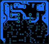
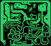
Does anybody perhaps have the layout of the quasi from Thiago in PDF format for diy etching.
I prefer the OP transistor setup.
Much appreciated !
I've applied some image transformations in order to try to help you.
Please check - and adjust - dimensions and any need of inverting the picture.
Regards,
Max.
Attachments
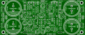
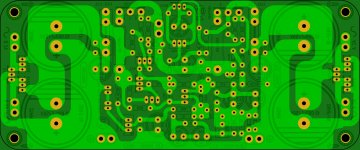
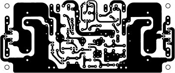
Open sprint layout-import gerbers-open the conteinning folder-one by one then import-chouse what visible-export jpg.Evening all !
Does anybody perhaps have the layout of the quasi from Thiago in PDF format for diy etching.
I prefer the OP transistor setup.
Much appreciated !
I hope this help
- Home
- Amplifiers
- Solid State
- Very simple quasi complimentary MOSFET amplifier