Member
Joined 2006
Well, that went pretty quickly as we hit 10 boards already, and then some. I don't want to clog up Ranchu's thread with a GB, so if there is more interest please PM me and maybe I squeeze in a few more boards. Thanks to above responders for quick reply.
X, if you need any help with PCB manufacturing, I could help in getting PCB like my CRC GB PCB that you have, of same specs people come to love. All the best, whichever way , its gonna sound awesome.
Hallo Guy's. Have you decided on how the mount the zobel and output coil when using Thiago's board ? Will it be ok to mount it on the speaker output connectors and use a universal board like Prasi has build?
universal thiele circuit
universal thiele circuit
You can also mount it on a simple shrink tube wrapped unit with coil (12 turns of 18ga on AA battery) and 4.7R 1W resistor inside the coil, located between the amp and the amp output connectors on the back panel. Prasi's universal board is also a good option but that requires one for each speaker.
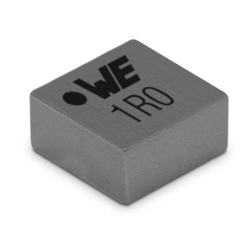
FWIW, a 1.2uH 7A inductor with only 15mOhm DCR is tiny and costs peanuts. I am going to try these or similar...
http://www.mouser.com/ds/2/445/74438357012-1102381.pdf

FWIW, a 1.2uH 7A inductor with only 15mOhm DCR is tiny and costs peanuts. I am going to try these or similar...
http://www.mouser.com/ds/2/445/74438357012-1102381.pdf

Last edited:
My PCB has Zobel
Thiele network, then....
Amp Stability techniques: Zobel et al.
http://www.diyaudio.com/forums/solid-state/120748-zobel-zobel.html?perpage=25
Zobel networks
Boucherot cell (Zobel network) values
thiele network - Pesquisa Google
http://leachlegacy.ece.gatech.edu/ece4445/downloads/zobel.pdf
@DACZ,
while l dedicate myself to the building of Cubie3 amp, my nephew would like to build this VSQCM amp making use of the (gorgeous) double sided boards that you preseted in the #1915 message.
Opening the gerber files, we noticed that:
1. both top and bottom soldermask files leave out one of the two holes made for the "+42V" power connector (female faston);
2. the "smdmask_bottom" file, which includes the mask only of 3 SMD capacitors, is a separate file from the "soldermask_bottom" file; could you explain us how we can correctly send it to the PCB fab? I/we are not expert about PCB design...
Could you kindly verify and advice us about these issues?
Many thanks
Nicola
Hallo Guy's. Have you decided on how the mount the zobel and output coil when using Thiago's board ? Will it be ok to mount it on the speaker output connectors and use a universal board like Prasi has build?
universal thiele circuit
I feel it shouldnt hurt to use version 2 of thiele ckt on speaker terminals.
universal thiele circuit
- Home
- Amplifiers
- Solid State
- Very simple quasi complimentary MOSFET amplifier

