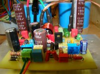
The second channel started up as easily as the first. I'll set them up to play in the shop for a few days before they graduate to a real system. I'll also take a peak with the oscilloscope to to check for obvious problems.
Thanks again,
Evan
Thanks again,
Evan
Attachments
Oh, yes, it would be very good. If I am not mistaken the first quasi scheme appeared in #45 post.Post #1 should be updated with the most recent correct schematic. The forum allows this.
C6 is feeding into 2k2 and 1k2.Sorry for no quote.....the question was for Hugh related to a previous post where he said 100uf is enough....
That's an effective impedance of ~776ohms.
Using a 220uF gets to a 170millisecond RC for well extended low bass response. 100uF gives only 78ms and will affect the low bass slightly, if this is inside the passband given by the input filters.
Post #1 should be updated with the most recent correct schematic. The forum allows this.
Consider it done. Here is the current schematic, kindly drawn by Dacz.
Attachments
R15 has been changed to 1k5 giving an effective RC of 89ms for 100uF, or 134ms for 150uFC6 is feeding into 2k2 and 1k2.
That's an effective impedance of ~776ohms.
Using a 220uF gets to a 170millisecond RC for well extended low bass response. 100uF gives only 78ms and will affect the low bass slightly, if this is inside the passband given by the input filters.
Since the input filter is set to 51ms (1u5F and 1k+33k) you will find that 100uF for C6 has an inaudible effect on very low bass response..
Last edited:
Andrew,
Have you assessed it subjectively in an audition?
I have heard it, and so has Christian, and our belief is that there is no enhancement of the bass response with C6 at 220uF over 100uF.
Had it improved, we would has suggested it, but there is no improvement, which is actually very good subjectively. Even profiling the response on LTSpice or actual measurement does not show up bigger bass response at 15Hz. There is the issue of the speaker, too, and maybe most speakers are not working too well at 15Hz. On LTSpice is see 1dB down at 13Hz with 220uF, and at 16Hz with 100uF. You cannot hear this at all; it should be up to 2dB and only then at source material with these very low frequencies.
Ergo: 100uF is adequate for all use with commonly used speakers. 220uF is larger, and does not improve things, so best to use 100uF which is quite small. Very similar issues concerned the shunt fb cap too, which we agreed does not improve beyond 1000uF.
Hugh
Last edited:
As a quiet follower of this thread I'm appreciative of the efforts being made here to develop what appears to be an exciting new amplifier.
But can I please ask the developers and followers here to check the spelling of the product's name?
"complimentary" and "complementary" are two different words, with distinctly different meanings. I would hope that all native-English speakers already know that.
I'm not a technician, and I don't understand the topology upon which this amplifier design is based, but it seems to me that "complimentary" is the wrong word.
Can someone, preferably with good technical AND English language skills, please confirm?
Yep. This happens occasionally...
How does your stereo system?
Complementary looks good. A quasi does not use complementary devices - they are same gender - but greek quasi word means it is unlike, a tricky imitation. Thimios could tell us the genuine (sic) of the word quasi!
HD
How does your stereo system?
Complementary looks good. A quasi does not use complementary devices - they are same gender - but greek quasi word means it is unlike, a tricky imitation. Thimios could tell us the genuine (sic) of the word quasi!
HD
Last edited:
Funny that !Looks like Andrew was agreeing with you.
Some fairly simple arithmetic does show that when the amplifier has the two passive filters at the input, then they determine what passes through a well behaved amplifier.
If one passes a signal which makes the amplifier misbehave, then something may become audible.
That here is not the case, the passband of the filters looks to be within the range that this amplifier can process well.
Expect the amp to sound good.
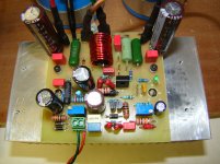
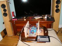
So I listened for a few hours on my old ariels. These little amps sound very good. They are by far the smallest amps I have built. A 4" piece of this 5.375" Wide Extruded Aluminum Heatsink - HeatsinkUSA seems OK for heatsink. Over the next week or so I'll box them up properly... dual mono power supply and dc speaker protection. Then I'll give them a try as part of my main system.
Thanks for the fun project,
Evan
Thanks for the fun project,
Evan
Attachments
Glad to see more and more builders after prasi's first pcb!Hi Ranchu32 and AKSA,
Thimios talked me into it!
Here is a layout of your amplifier as per post # 158. I havent yet refined it and I thought its better to invite some comments before spending too much time into it. much of the PCB space is wasted which can be optimized later. So, its just a draft, as draft as it can be.
reg
Prasi
edit: haven't read through the entire thread, but I understand that Q4 has to be mounted on o/p MOSFET + positive rail decoupling caps could be closer to mosfet pins.
Glad to see more and more builders after prasi's first pcb!
Thanks Thimios,
to put the credit where it really belongs, i think the popularity is due to the wonderful support put forth by both the designers Hugh and Christian!...
 .Hugh's clear explanation regarding the amp's working, design evolution and why it should sound wonderful and Christian's guidance on values of components and mech construction has lot to do with its popularity.
reg
Prasi
Absolutely right!Thanks Thimios,
to put the credit where it really belongs, i think the popularity is due to the wonderful support put forth by both the designers Hugh and Christian!...
reg
Prasi
The design is the start of all.

Consider it done. Here is the current schematic, kindly drawn by Dacz.
Dear Ranchu32,
Can you teach me how is the value of C8 (OPTN)?
Thanks you very much.
Best regards,
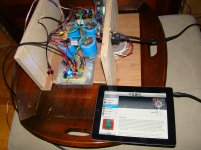
I have been listening to this as my main amp with 25v rails for past week and still enjoying it immensely. Very balanced and does a great job with all genres. Long term progress report is excellent, still.
Currently listening to this track. Here is recording in mono of left channel. Change extension to .mp3 to listen.
Currently listening to this track. Here is recording in mono of left channel. Change extension to .mp3 to listen.
Attachments
Last edited:

Dear Ranchu32,
Can you teach me how is the value of C8 (OPTN)?
Thanks you very much.
Best regards,
Hi ThaiKy, welcome and thanks for your interest in our amp. It has been determined that C8 is unnecessary provided the recommended transistors are used in in conjunction with the board layouts developed and tested thus far.
- Home
- Amplifiers
- Solid State
- Very simple quasi complimentary MOSFET amplifier