Here is PCB with final figures.
Tested and working.
Sprint attached file.
Regards
Thiago
Hi, Thiago
What schematic do you use for this layout?
regards
Amp#1 and Amp#2 test notes..
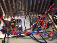
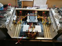
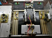
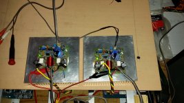
An update on my progress: I have my Amp#1 (IRFP240/MJL3281) and Amp#2 (IRFP250/MJL4281) running in a test setup now (a hollowed-out and repurposed Denon amplifier). On both amps there is a 1nF cap on BJT base-collector.
About cooling: I discovered that horizontal mounting is a bad idea, as the heat gets trapped under the PCB, and temperatures quickly become unhealthy, especially in the long run. I use a slow fan now in testing, to get the air circulating under the boards. If I build a "real" amplifer with these boards, I will definitely mount them vertically.
I am in the process of trying out different rail voltages and Iq levels, and comparing the amps.
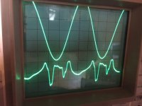
A HP339A is used for THD measurement, and sends the distortion residual to my O'scope. In the attached pictures, the sine test signal is on top, and the distortion shape below (same way as Nelson Pass does in many of his posts and articles, in case you may be familiar with those).
I testing with up to 55v rails, but have settled on 35V rails for the moment.
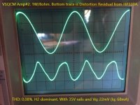
So far Amp#2 is looking the best: It seems to like 20-22mV Vq (Quiescent voltage). This gives the results shown in the two screenshots.
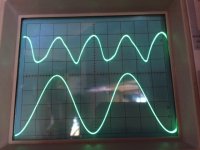
At 1w level the distortion residual looks nice, almost a class A shape, clearly H2 dominant. Over about 6Vrms this changes though, and the distortion takes on a rather peculiar shape, which is new to me - I assume it is a quasi-mosfet trait. But at both 1w and 50w output (in 8ohm load), the THD stays around 0,08%.
Raising the quiescent to around 50-60mV, gives a slight improvement up to 6Vrms, but above that is actually becomes worse than at the lower Vq. Then if I go very high on Quiescent, up to 180-200mV, it looks better at all power levels, but of course this level of idle power dissipation is not ideal.
Amp#1 is somewhat surprisingly (to me), not performing that well. It needs more than double the Vq, and even so, the THD goes up near 0,4% at 50W.
I would like to find out if this significant difference stems primarily from the Mosfet or the BJT, so will probably swap out the IRFP240 on Amp#1 for a IRFP250, and see what happens...")
PS.: The 1W picture is upside down for some reason..
An update on my progress: I have my Amp#1 (IRFP240/MJL3281) and Amp#2 (IRFP250/MJL4281) running in a test setup now (a hollowed-out and repurposed Denon amplifier). On both amps there is a 1nF cap on BJT base-collector.
About cooling: I discovered that horizontal mounting is a bad idea, as the heat gets trapped under the PCB, and temperatures quickly become unhealthy, especially in the long run. I use a slow fan now in testing, to get the air circulating under the boards. If I build a "real" amplifer with these boards, I will definitely mount them vertically.
I am in the process of trying out different rail voltages and Iq levels, and comparing the amps.
A HP339A is used for THD measurement, and sends the distortion residual to my O'scope. In the attached pictures, the sine test signal is on top, and the distortion shape below (same way as Nelson Pass does in many of his posts and articles, in case you may be familiar with those).
I testing with up to 55v rails, but have settled on 35V rails for the moment.
So far Amp#2 is looking the best: It seems to like 20-22mV Vq (Quiescent voltage). This gives the results shown in the two screenshots.
At 1w level the distortion residual looks nice, almost a class A shape, clearly H2 dominant. Over about 6Vrms this changes though, and the distortion takes on a rather peculiar shape, which is new to me - I assume it is a quasi-mosfet trait. But at both 1w and 50w output (in 8ohm load), the THD stays around 0,08%.
Raising the quiescent to around 50-60mV, gives a slight improvement up to 6Vrms, but above that is actually becomes worse than at the lower Vq. Then if I go very high on Quiescent, up to 180-200mV, it looks better at all power levels, but of course this level of idle power dissipation is not ideal.
Amp#1 is somewhat surprisingly (to me), not performing that well. It needs more than double the Vq, and even so, the THD goes up near 0,4% at 50W.
I would like to find out if this significant difference stems primarily from the Mosfet or the BJT, so will probably swap out the IRFP240 on Amp#1 for a IRFP250, and see what happens...
PS.: The 1W picture is upside down for some reason..
Attachments
Last edited:
Hi guys
I believe there is a higher power version of this quasi along with a tested pcb. Am I correct ?
I have a few pcb of the regular version but I have just bought a rack mount power amp which is dual mono. Each channel has a 200VA, 70Vct transfo therefore +/- 50Vdc rails and cooling fan.
My load will be 4 ohm speaker.
Would the high power version be ok at 50Vdc rails and a 4 ohm load ?
If that is not suitable, I’ll go with the FH9-HV from XRK
Happy New Year to all !
Thanks
Eric
Last edited:
JVHB,
To identify the problem in #1 I would compare all voltages between the two amps, at the same voltage rails, with no music. Compared the good amp with the bad on basic of DC voltages along. If they are the same, and in particularly if the same bias voltage leads to very different quiescents, I would look at the mosfet in the output stage of #1. I suspect you may have a fake mosfet; or even a wide tolerance on its parameters.
I presume you have not yet connected speakers and listened to the sound quality? This is a very tried design now, and the pcb layout is without peer. I believe it comes back to outputs, and these huge differences indicate bad active output, oscillation or undercompensation. If you change that output mosfet, and measure again, if the figures are unchanged then I would look at the output on a CRO without signal, and if OK, I would increase the compensation by 25%.
Hope this is helpful,
Hugh
Amp#1 is somewhat surprisingly (to me), not performing that well. It needs more than double the Vq, and even so, the THD goes up near 0,4% at 50W.
To identify the problem in #1 I would compare all voltages between the two amps, at the same voltage rails, with no music. Compared the good amp with the bad on basic of DC voltages along. If they are the same, and in particularly if the same bias voltage leads to very different quiescents, I would look at the mosfet in the output stage of #1. I suspect you may have a fake mosfet; or even a wide tolerance on its parameters.
I presume you have not yet connected speakers and listened to the sound quality? This is a very tried design now, and the pcb layout is without peer. I believe it comes back to outputs, and these huge differences indicate bad active output, oscillation or undercompensation. If you change that output mosfet, and measure again, if the figures are unchanged then I would look at the output on a CRO without signal, and if OK, I would increase the compensation by 25%.
Hope this is helpful,
Hugh
I think you are telling us that the rightmost pic with the dominant 2nd harmonic is the 1W into 8r0 test. That shows a "clean" no crossover distortion residual. That is to be expected when one keeps the output current below the 2*Bias current level.An update on my progress: I have my Amp#1 (IRFP240/MJL3281) and Amp#2 (IRFP250/MJL4281) running in a test setup now (a hollowed-out and repurposed Denon amplifier). On both amps there is a 1nF cap on BJT base-collector.
About cooling: I discovered that horizontal mounting is a bad idea, as the heat gets trapped under the PCB, and temperatures quickly become unhealthy, especially in the long run. I use a slow fan now in testing, to get the air circulating under the boards. If I build a "real" amplifer with these boards, I will definitely mount them vertically.
I am in the process of trying out different rail voltages and Iq levels, and comparing the amps.
A HP339A is used for THD measurement, and sends the distortion residual to my O'scope. In the attached pictures, the sine test signal is on top, and the distortion shape below (same way as Nelson Pass does in many of his posts and articles, in case you may be familiar with those).
I testing with up to 55v rails, but have settled on 35V rails for the moment.
So far Amp#2 is looking the best: It seems to like 20-22mV Vq (Quiescent voltage). This gives the results shown in the two screenshots.
At 1w level the distortion residual looks nice, almost a class A shape, clearly H2 dominant. Over about 6Vrms this changes though, and the distortion takes on a rather peculiar shape, which is new to me - I assume it is a quasi-mosfet trait. But at both 1w and 50w output (in 8ohm load), the THD stays around 0,08%.
Raising the quiescent to around 50-60mV, gives a slight improvement up to 6Vrms, but above that is actually becomes worse than at the lower Vq. Then if I go very high on Quiescent, up to 180-200mV, it looks better at all power levels, but of course this level of idle power dissipation is not ideal.
Amp#1 is somewhat surprisingly (to me), not performing that well. It needs more than double the Vq, and even so, the THD goes up near 0,4% at 50W.
I would like to find out if this significant difference stems primarily from the Mosfet or the BJT, so will probably swap out the IRFP240 on Amp#1 for a IRFP250, and see what happens...
PS.: The 1W picture is upside down for some reason..
But that confuses me. 1W into 8r0 is equivalent to 500mApk and 4Vpk into the resistor.
What dummy load resistor did you use? 8ohms, or 100ohms, or open circuit and just the Output Zobel as the load?
The middle pic is the same amplifier, but with the output level increased to 50W into 8ohms. Is that the correct reading of your post?
This pic showing the high frequency artefacts in the distortion residual, is typical of gross crossover distortion.
This happens in all ClassAB amplifiers and in Push-Pull ClassA amplifiers, if and when the output current exceeds 2*bias current **.
50W into 8ohms is equivalent to 3.536Apk and would require the bias to be set to >1.8A to keep the output below that 2*bias current to avoid the crossover distortion.
** There is a Class of operation where the bias slides with output voltage and one can obtain a bit more output current than the strict 2*bias current limit for ClassA operation. JLH's 1969 and later are of this type. Both the upper and lower output devices remain in control of the output signal and this defines ClassA. When one or other device stops controlling and leaves the other device to control the output signal that we have transitioned beyond ClassA. This condition can be with the non controlling device passing a zero current, or passing a near constant current.
Last edited:
Thanks
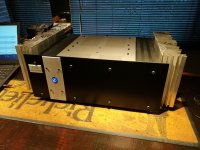
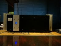
Thanks to all involved with getting this amp running as good as it sounds. Have got it currently on a pair of Spendor S100's, sounds extremely good, but it is on its way to my son in law, and he uses PSB speakers. Hope it sounds good on them as well !! Couldn't get it over my heart to cut the heatsinks, gets hot in Africa and we know how to party !! Special thanks to Hugh for his patience with all the answers !!
Thanks to all involved with getting this amp running as good as it sounds. Have got it currently on a pair of Spendor S100's, sounds extremely good, but it is on its way to my son in law, and he uses PSB speakers. Hope it sounds good on them as well !! Couldn't get it over my heart to cut the heatsinks, gets hot in Africa and we know how to party !! Special thanks to Hugh for his patience with all the answers !!
Attachments
High Output VSQC...
Finally built the higher power version of VSQC with FQA40N25 mosfet and MJL4281AG bjt output transistors. I have to say that it sounds just like the normal version with IRFP240 and MJL3281. Very good! I also used the led options at D9/D10 and D7 rather than zeners and diodes. The blue leds need a piece of electrical tape to avoid blinding me while setting up. I'm running these at +-52VDC with 35mV bias across R20 (0.33 ohm) and the heatsinks do get warm, 47 C (117 F). Q3 is standing with no heatsink and is running about 55 C (131 F). The amps are built on DACZ boards and schematic in post 1231.
The sound of this amp is excellent. Nice low end and very smooth sounding through the entire audible range. These amps are near silent with no music playing. This high output version is a good option for people wanting a little more overhead or if you already have a suitable power supply.
On a side note, I found 2 different batches of 3.3v zener diodes, 1N4728, measured out of range. First batch measured 1.5v and second batch measured 3.8v. These were different manufacturers from different vendors. I then ended up using the obnoxiously bright blue leds.
Thanks again to everyone who has promoted this project. Now if I can only finish building enclosures for the several naked amps around my workbench....
Attachments
That's the coolest idea I've heard for a while! You could make a neat steam punk amp with a cylinder head or barrel. I like it.....That's some heat sinking! Have you considered attaching it to an aircooled motorcycle? Actually that would make a nice add-on to a DIY amp. Heatsinking by GT380 cylinder head.
Hello, I have been away from DIY audio projects for a while, as work and general life issues got in the way
So alas, I have not made any progress with my amp building, but hope to get back to it soon..
In the meantime, two different Mosfets have arrived, so now I can try out the FDA59N25 and the FDA38N30 - when time permits. Looking forward to that.
Hi AndrewT, sorry for the lack of reply, but better late than never they say.
I have attached the 1W output picture here again, now with explanatory text to avoid any confusion.
Yes the testing is with 8ohm load resistor, Zobel output network is in place on amp PCB, and test signal is 1 Khz. If I test without a load attached, the Distortion residual is basically a flat line, as there is no measureble distortion.
The statements you are making regarding the shape of distortion residual traces (as fed from HP339A to Oscilloscope) are incorrect:
A clean H2 dominant residual is not a given at 1W output, regardless of Iq level.
Some topologies/designs have it (often relatively simple amps), but most solid state amplifiers (that I test) have a much more mixed harmonic signature.
And it is not necessarily a result of ClassA biasing, as this amp is running on only 68mA Iq in the test. But as I wrote earlier, the shape does remind me of a Class A amp, so that is quite nice.
Crossover distortion is usually not that visible (if at all) at any output level in a correctly biased amplifier - in my experience. Even for pure ClassB, crossover distortion is not usually a dominant factor (as shown by Douglas Self) in measurements - only in case of underbiasing, will it dominate the residual trace shape (or FFT results).
This is based on my observations from benchtesting 100's of amplifiers with HP339A (and a HP3325B for square waves etc.), Oscilloscope and a passive load switchable from 2 ohms up to 16 ohm.
---
It is (finally!) feeling like spring here, so will leave the electronics for now, and venture outside. A good weekend to you all
So alas, I have not made any progress with my amp building, but hope to get back to it soon..
In the meantime, two different Mosfets have arrived, so now I can try out the FDA59N25 and the FDA38N30 - when time permits. Looking forward to that.
I think you are telling us that the rightmost pic with the dominant 2nd harmonic is the 1W into 8r0 test. That shows a "clean" no crossover distortion residual. That is to be expected when one keeps the output current below the 2*Bias current level.
But that confuses me. 1W into 8r0 is equivalent to 500mApk and 4Vpk into the resistor.
What dummy load resistor did you use? 8ohms, or 100ohms, or open circuit and just the Output Zobel as the load?
The middle pic is the same amplifier, but with the output level increased to 50W into 8ohms. Is that the correct reading of your post?
This pic showing the high frequency artefacts in the distortion residual, is typical of gross crossover distortion.
This happens in all ClassAB amplifiers and in Push-Pull ClassA amplifiers, if and when the output current exceeds 2*bias current **.
50W into 8ohms is equivalent to 3.536Apk and would require the bias to be set to >1.8A to keep the output below that 2*bias current to avoid the crossover distortion. (...)
Hi AndrewT, sorry for the lack of reply, but better late than never they say.
I have attached the 1W output picture here again, now with explanatory text to avoid any confusion.
Yes the testing is with 8ohm load resistor, Zobel output network is in place on amp PCB, and test signal is 1 Khz. If I test without a load attached, the Distortion residual is basically a flat line, as there is no measureble distortion.
The statements you are making regarding the shape of distortion residual traces (as fed from HP339A to Oscilloscope) are incorrect:
A clean H2 dominant residual is not a given at 1W output, regardless of Iq level.
Some topologies/designs have it (often relatively simple amps), but most solid state amplifiers (that I test) have a much more mixed harmonic signature.
And it is not necessarily a result of ClassA biasing, as this amp is running on only 68mA Iq in the test. But as I wrote earlier, the shape does remind me of a Class A amp, so that is quite nice.
Crossover distortion is usually not that visible (if at all) at any output level in a correctly biased amplifier - in my experience. Even for pure ClassB, crossover distortion is not usually a dominant factor (as shown by Douglas Self) in measurements - only in case of underbiasing, will it dominate the residual trace shape (or FFT results).
This is based on my observations from benchtesting 100's of amplifiers with HP339A (and a HP3325B for square waves etc.), Oscilloscope and a passive load switchable from 2 ohms up to 16 ohm.
---
It is (finally!) feeling like spring here, so will leave the electronics for now, and venture outside. A good weekend to you all
Attachments
AndrewT is no more and breathed his last on 12th March, may god rest his soul in peace.
JLH 10 Watt class A amplifier
JLH 10 Watt class A amplifier
Crossover distortion is usually not that visible (if at all) at any output level in a correctly biased amplifier - in my experience. Even for pure ClassB, crossover distortion is not usually a dominant factor (as shown by Douglas Self) in measurements - only in case of underbiasing, will it dominate the residual trace shape (or FFT results).
This is another case of measuring the wrong thing. Or not measuring everything that matters
The problem I've run into previously is that the loop gain at crossover (usually) goes awry. Depending on your topology your ability to source/sink current can also goes away.
Which is fine if you're driving a sine wave into a resistor but not if the load is complex. You may find that the diff amp clips in an attempt to compensate.
I've managed to screw device turn on/off - maked a signal controlled oscillator
Vale Andrew T
- Home
- Amplifiers
- Solid State
- Very simple quasi complimentary MOSFET amplifier