Progress with Phunk PCB..
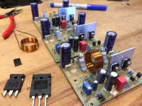
Hi, just to keep this great thread going, here is a picture of my progress with the two-tone (blue on bottom) Phunk boards")
At this stage, I am building up 3 boards with identical quality (and partially matched) components, except for the outputs. The idea being to have some fun comparing the amps with different outputs.
I am planning to do:
Amp #1: IRFP240/MJL3281
Amp #2: IRFP250/MJL4281
Amp #3: FQA40N25/MJL4281 (- and possibly improvise dual 4281 devices, to better match the FQA40N25)
Amp#1 might be up and running later this afternoon.
I know the design is well proven already, so no one is holding their breath to see my results, but I think this will be the first build running on Phunk Pod PCB anyways..
Also, I intend to measure and compare THD and FFT with the different outputs, so that might be something of value to others around here.
The FQA40N25 is still not in stock at Mouser though, so I don't know when I will get Amp#3 going. I had a look at FDA38N30 as an alternative, but the Forward Transconductance is only 6, and as I understand it, a higher value is desirable here. Or?.. I think Hugh may have written something about that, but can't find it now.
A point of interest: As you may notice from the picture, I have not mounted the Q3 VAS in sandwich with the BJT output under the PCB, as Uncle Phunk had designed it to. Instead I decided to mount it upright, and since the footprint is in-line with the Q5 (Phase inverter), it was very convienient to mount both these SA1381 together on a simple flat heatsink plate. Since the Q3 doesn't need the direct thermal coupling to the output NPN (afaik), this should be a better solution, and keep both Q3 and Q5 cooled, even with 55V rails.
I will use a BD139 as spacer under the PCB, in place of Q3. Almost couldn't get myself to cut the legs off a perfectly good little transistor, and I have to cut two more
Edit: Forgot to mention, that the "fighting soldier style" source/emitter resistors for the outputs, are 1 ohm in parallel with 0,47 ohm (3W), giving me 0,32 ohm. A bonus of this solution, is that it's super easy to clip on to them for measurements!
Hi, just to keep this great thread going, here is a picture of my progress with the two-tone (blue on bottom) Phunk boards
At this stage, I am building up 3 boards with identical quality (and partially matched) components, except for the outputs. The idea being to have some fun comparing the amps with different outputs.
I am planning to do:
Amp #1: IRFP240/MJL3281
Amp #2: IRFP250/MJL4281
Amp #3: FQA40N25/MJL4281 (- and possibly improvise dual 4281 devices, to better match the FQA40N25)
Amp#1 might be up and running later this afternoon.
I know the design is well proven already, so no one is holding their breath to see my results, but I think this will be the first build running on Phunk Pod PCB anyways..
Also, I intend to measure and compare THD and FFT with the different outputs, so that might be something of value to others around here.
The FQA40N25 is still not in stock at Mouser though, so I don't know when I will get Amp#3 going. I had a look at FDA38N30 as an alternative, but the Forward Transconductance is only 6, and as I understand it, a higher value is desirable here. Or?.. I think Hugh may have written something about that, but can't find it now.
A point of interest: As you may notice from the picture, I have not mounted the Q3 VAS in sandwich with the BJT output under the PCB, as Uncle Phunk had designed it to. Instead I decided to mount it upright, and since the footprint is in-line with the Q5 (Phase inverter), it was very convienient to mount both these SA1381 together on a simple flat heatsink plate. Since the Q3 doesn't need the direct thermal coupling to the output NPN (afaik), this should be a better solution, and keep both Q3 and Q5 cooled, even with 55V rails.
I will use a BD139 as spacer under the PCB, in place of Q3. Almost couldn't get myself to cut the legs off a perfectly good little transistor, and I have to cut two more
Edit: Forgot to mention, that the "fighting soldier style" source/emitter resistors for the outputs, are 1 ohm in parallel with 0,47 ohm (3W), giving me 0,32 ohm. A bonus of this solution, is that it's super easy to clip on to them for measurements!
Attachments
Last edited:
You could leave the legs of the BD139 and cover with shrink tube. In case of emergency requiring needed BD139, you can always come back and pull out your backup reserve stash.
I did contemplate something like that, but decided it just wasn't worth the bother for the sake of a 20 cent transistor...
And I didn't get it running today, as I got bogged down with decisions, and some drilling and tapping which took much longer than expected - as these mechanical jobs often do. Maybe tomorrow, if work doesn't get in the way..
JV,
The 38N or 40N is just fine. In the topology used, the transconductance of these devices is large driving by the reciprocal of the source resistor; in both cases using a 0.33R resistor the transconductance is dominated by 1/0.33, so around S=3, is quite OK. Only if a mosfet is used in common source is the transconductance important.
Nice work!
Hugh
Last edited:
Guy's/Hugh, plse help with some info. I know the preferable bias is between 33mV and 45mV. My bias is currently 33mV. I have more than enough heat sink available on the amp. What values did you use ? The amp sound great but I am tempted to increase bias to 45mV to see if there can be any more improvement ! Using IRFP250/ MJL3281 on OP running on +-40Vdc rails.
Using IRFP250/ MJL3281 on OP running on +-40Vdc rails.Hi Prasi,
No, I haven’t tried yet with this amp. This one has BJT and vertical hexFET so potentially could suffer from thermal runaway if Vbe multiplier temp comp is not set just right. It’s a bit more sporty to push 1.5amps through it. I think Hugh has told me before that there wouldn’t be much to be gained sonically and it would just waste a lot of heat and be liable to blow up.
No, I haven’t tried yet with this amp. This one has BJT and vertical hexFET so potentially could suffer from thermal runaway if Vbe multiplier temp comp is not set just right. It’s a bit more sporty to push 1.5amps through it. I think Hugh has told me before that there wouldn’t be much to be gained sonically and it would just waste a lot of heat and be liable to blow up.
there wouldn’t be much to be gained sonically and it would just waste a lot of heat and be liable to blow up
However, Jan, give it a try - it might even sound better, stranger things have happened!
I would try 49mV, that will be close to 150mA quiescent.
If it does not get too hot and sounds very good, it might be another option........
Cheers,
Hugh
Speaking of quiescent, I managed to power up my Amp #1 today (finally!), but I couldn't get the Iq any lower than about 49mV on the 0R32 mosfet source resistor, and with 40V rails. And the first (short) test, showed a rather high 0,4% THD@1W using my HP339A for measurement. DC offset was alright. But something must be amiss I think..
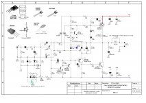
It is built according to Dacz schematic Rev 2., with D7 3V3 zener, instead of blue LED, and SA1381 for both Q3 and Q5. Outputs are IRFP240 and MJL3281.
If I change the R17 BJT base resistor to 4R7, should I also increase the R16 on the mosfet gate accordingly? Or is there a better way to bring Iq levels down a bit?
Attachments
THD does not tell you much. Most of it will be H2 and H3, essentially not an issue for musicality.
It does seem a little high, however, I would expect no more than 0.06% at +20dB output (12.5W into 8R). It could be oscillation, can you see anything amiss on the CRO?
I would not change the base or gate stoppers. They are pretty right as they are. If anything, I'd add 2.2nF between base and collector of the quasi npn, Q7.
Hugh
Hugh
THD does not tell you much. Most of it will be H2 and H3, essentially not an issue for musicality.
It does seem a little high, however, I would expect no more than 0.06% at +20dB output (12.5W into 8R). It could be oscillation, can you see anything amiss on the CRO?
I would not change the base or gate stoppers. They are pretty right as they are. If anything, I'd add 2.2nF between base and collector of the quasi npn, Q7.
Hugh
I am hardly in a position to argue with someone as experienced and accomplished as you, but in my opinion, THD says a whole lot! I am a novice in building amplifiers, but somewhat experienced in testing amplifiers, and relating the THD numbers in conjunction with the distortion residual shape, to amplifier performance and topology. Based on this experience, I have found I can usually predict audio performance fairly reliably, based on these objective results (Ceteris paribus, as they say).
- But what you probably meant, was that a THD figure alone, without context or background, doesn't tell you if a given amplifier will sound good (unless the THD is several %, in which case it is likely either a SET amp, or a defective amp) - that I can agree with in any case
But in this situation, I knew from reading through this thread, that a correctly built amp should measure better, which told me right away that something was not quite right with my Amp#1.
I have now added a 1nF cap from Base to Collector, and changed the 3V3 zener to a blue led with Vf 2,83.
Result: THD at 1W dropped from 0,4 to 0,07% (with Vq 50mv, i.e. Iq 156mA), and I got a much better range of adjustment of quiescent - it can now go down to 4mV). Distortion residual shape (from my HP339) looks relatively good, but not excellent. At 20W output it is still okay, but nearing full power, it gets ugly. I look forward to seeing what changes a different Mosfet will bring. I will fire up my ARTA setup for FFT testing, once I have all three amp boards running stable and partially optimized, and some time around that, I will make a stereo amp and actually connect some speakers.
So far so good, next week the adventure (and testing) continues
- Home
- Amplifiers
- Solid State
- Very simple quasi complimentary MOSFET amplifier