A few more toys
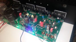
Complete system including modular preamp and selector with DAC.
My sound card is not sufficient to measure the system anymore, time to get a new one..
Regards
I wish I could listen to it...
BTW I am using tuned E-MU 0202 USB!
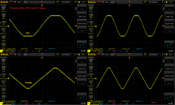
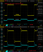
New Year, new projects must be made. So here it comes, new version of Cliffjumper IPS.
It is very simple, VAS is running threw a LTP current mirrors so there is no problem with ''unknown'' VAS bias. There is still a bit of work to be done with it but so far it sings really OK.
It is very simple, VAS is running threw a LTP current mirrors so there is no problem with ''unknown'' VAS bias. There is still a bit of work to be done with it but so far it sings really OK.
Attachments
-
 cliffjumper_mk2_clipping.png111.2 KB · Views: 769
 -
 cliffjumper MK2.jpg140.3 KB · Views: 344
 -
 cliffjumper_mk2_thd_single.png76 KB · Views: 119
 -
 cliffjumper_mk2_thd_plots.png40.8 KB · Views: 121
 -
 cliffjumper_mk2_capload.png79.1 KB · Views: 77
 -
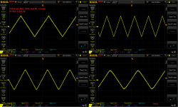 cliffjumper_mk2_triangle.png124.7 KB · Views: 690
 -
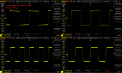 cliffjumper_mk2_square.png107.1 KB · Views: 707
 -
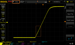 cliffjumper_mk2_slewrate.png29.3 KB · Views: 716
 -
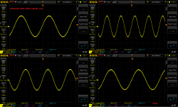 cliffjumper_MK2_sine.png121.9 KB · Views: 741
 -
Cliffjumper MK2 - schematic.pdf36.1 KB · Views: 265
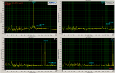
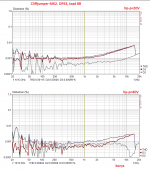
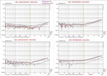
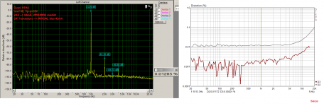
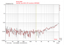
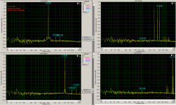
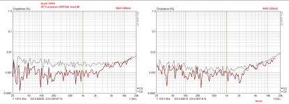
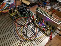
Just for curiosity I have made a small comparison in two the same circuits but differend output devices and differend bias settings.
The setup contains the same IPS boards, the same OPS and emu204 as a measurement device.
Reasults show way better performance of good old 2SJ201/2sSK1530 over IRFP240/9240 at the similar bias settings.
The third harmonic is going down a lot with higher bias, heh it looks like a warm heatsing=warm sound. And I must say the Toshiba mosfets ounds very, very nice and smooth.
Regards
Attachments
Last edited:
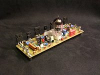
I have made a small change to the schemetic to increase GM and PM, so now a few other types of tubes can be fitted in the same ecc88 socket.
So far I have tested ECC88 (a few manufacturers), 6N23P and 6N30Pi (this one needs to be biased at -2,5V to -3V + DC heater).
Recently I have made also tests with IRF610 and IRF 9610 as a drivers in BJT OPS unit. IRF's are biased to 50mA and are driving 3 pairs of 2sc5200/2sa1943.
Regardless THD plots first sonic impression is there is less kick and power in bass area + much smoother top end. After further tests I will post some resaults.
Attachments
I have made a small change to the schemetic to increase GM and PM, so now a few other types of tubes can be fitted in the same ecc88 socket.
So far I have tested ECC88 (a few manufacturers), 6N23P and 6N30Pi (this one needs to be biased at -2,5V to -3V + DC heater).
Recently I have made also tests with IRF610 and IRF 9610 as a drivers in BJT OPS unit. IRF's are biased to 50mA and are driving 3 pairs of 2sc5200/2sa1943.
Regardless THD plots first sonic impression is there is less kick and power in bass area + much smoother top end. After further tests I will post some resaults.
Serious built Boris, it does look great..
")
I hope you succeed and will be the best performance you ever achieved.
Too much free time always results with another project
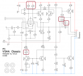
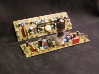
This time it names Quasi VSHA. Not the best, not the worst but I like it.
To make long story short:
-ECC88 input
-mosfet VAS cascode
-quasi n-mosfet output
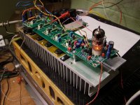
As I like simple stuff this one makes me really happy. It will need some more listening sessions and some fine tuning but basicly the circuit is in ''ready to go'' version.
Any advices, upgrades allways welcome.
Bellow all documentation.
Regards Peter
This time it names Quasi VSHA. Not the best, not the worst but I like it.
To make long story short:
-ECC88 input
-mosfet VAS cascode
-quasi n-mosfet output
As I like simple stuff this one makes me really happy. It will need some more listening sessions and some fine tuning but basicly the circuit is in ''ready to go'' version.
Any advices, upgrades allways welcome.
Bellow all documentation.
Regards Peter
Attachments
-
Quasi VSHA V6.5 - Documentation ZIP.zip274 KB · Views: 203
-
 quasiVSHA_VP0109N3.png63.9 KB · Views: 115
 -
 quasiVSHA_irfp250N_thd_bias.png22.1 KB · Views: 116
 -
 quasiVSHA_irfp250_thd_plots.png104.7 KB · Views: 127
 -
 QuasiVSHA_bias_thd_plot.png37.7 KB · Views: 220
 -
 quasi_amp2.jpg167.7 KB · Views: 253
 -
 quasi_amp.jpg149.4 KB · Views: 417
 -
 measurement setup.jpg300.5 KB · Views: 176
Last edited:
Peter,
I really like your tube/mosfet hybrid. I do have some concern about the very low B+ 12V for the tube, however. Would you consider using a HT supply for it to reduce the THD a little and add a bit of slam and impact?
It is beautifully implemented, wonderful work, a very compact, elegant pcb.
Hugh
I really like your tube/mosfet hybrid. I do have some concern about the very low B+ 12V for the tube, however. Would you consider using a HT supply for it to reduce the THD a little and add a bit of slam and impact?
It is beautifully implemented, wonderful work, a very compact, elegant pcb.
Hugh
Hi Kay,
I rechecked and I was wrong; the B+ appears to be 45V rail on Borys' amp, my apologies.
He mentions 1.7mA and 34V Vak. This is marginal for a 12AU7 and also for a ECC88, though Broskie recommends Vak 100V and 10mA. But I know that it sounds good because Borys told us, so clearly it's not too low!
I would probably use a cathode follower rather than a plate load, but it's a brilliant circuit which accommodates the lower voltages of transistor amplifiers.
I offer congratulations to Piotr, clever work.
Hugh
Big Thanks for kind words !!
The tube supply is stabilised at approx 65-70VDC (voltage doubler PSU). With active load the anode voltages are approx 57Vdc (measured from GND), the grid is at 1,6VDC. With higher tube bias it was hard to get it to work linear, I had problem to tune compensation to make it work perfect. With lower bias (aproxx 5,5mA) triode started to work perfect. Maybe with resistive anode load it would be better at 10mA. I will try it later on.
I will remove C5 and C9 and try how does work.
Yes LED1 and R9 are not necessary. LED1 is only kind of diagnostics + lighting the tube from under the socket, after the tube is heated, current starts to flow through the cathodes and LED1 is starting to glow (so I know it is operating). R9 only takes a bit of the thermal losses from T3, I didn't know what bias amount I will use (10mA * 50V = 500mW = wartm TO92).
I have no experience with WIMA MKS4, are they any good for input DC blocking ?
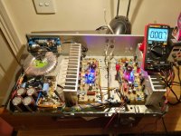
I have prepared some very temporary home (with solid core wiring) for the stereo setup and i next couple of days I have listen to it.
Bias is very stable, offset sits in the right spot all the time.
Regards
Peter
The tube supply is stabilised at approx 65-70VDC (voltage doubler PSU). With active load the anode voltages are approx 57Vdc (measured from GND), the grid is at 1,6VDC. With higher tube bias it was hard to get it to work linear, I had problem to tune compensation to make it work perfect. With lower bias (aproxx 5,5mA) triode started to work perfect. Maybe with resistive anode load it would be better at 10mA. I will try it later on.
I will remove C5 and C9 and try how does work.
Yes LED1 and R9 are not necessary. LED1 is only kind of diagnostics + lighting the tube from under the socket, after the tube is heated, current starts to flow through the cathodes and LED1 is starting to glow (so I know it is operating). R9 only takes a bit of the thermal losses from T3, I didn't know what bias amount I will use (10mA * 50V = 500mW = wartm TO92).
I have no experience with WIMA MKS4, are they any good for input DC blocking ?
I have prepared some very temporary home (with solid core wiring) for the stereo setup and i next couple of days I have listen to it.
Bias is very stable, offset sits in the right spot all the time.
Regards
Peter
Attachments
Last edited:
Peter,
I built a hybrid amp using a 12AU7 and a ETI SS amp more than twenty years ago but used a slightly different topology which was very different sonically.
I put the triode OUTSIDE the fb loop. You have put the triode into the amp, and used global fb to linearise it. This gives excellent figures BUT the sound of the tube is muted because it is played down by the loop gain.
If you put the triode at the output of your SS, then proportion the output of the tube to your normal fb signal and apply it to the inverting node, you put 'tube' sound directly into the fb path and confer the tube sound.
BUT you need more voltage on the tube because you are dealing with higher signals, although you can dimension the output lower so it does not overload the tube.
If you use a cathode follower, you can keep the output to fb node in phase, and ensure the lower output is low too.
You have a simpler SS amp, but you do need to accommodate the slow tube turn on so there is limited gain during those critical 11 seconds.
I saw a circuit from Generosimo in Italy many years ago which was very similar to yours, but not as refined in the schematic. Again, my congratulations to a great design.
Hugh
Thanks Hugh
I will try something new for sure. If You will have a bit of time and find me some examples so I can start with and develop further, can be even simple drawing on the piece of paper.
I like ''to dig'' in the amplifiers so it is only mater of time to come up with something new.
BTW
I am working on quasi output stage with voltage gain approx 2 times and swinging from rail to rail. So let me say with +/-50VDC supply rails it will need only +25V and -25V to swing full -50V + 50V at the output, it may come handy for next time.
Thanks
Peter
Last edited:
WIMA MKS4 are not good as a input dc bolocking cap
http://www.mouser.com/ds/2/440/e_WIMA_MKS_4-1139797.pdf
mks is a metalised polyester.
I did reasearch online and they say the best type of generic input cap is metalised polypropene. I can get them for approx 0.5-1nzd each at rs components.
Just a quick question, how much dc voltage maximum appears at amp output when powering up and shutting down. I am considering to build this circuit without any relays.
WIMA MKS4 are not good as a input dc bolocking cap
http://www.mouser.com/ds/2/440/e_WIMA_MKS_4-1139797.pdf
mks is a metalised polyester.
I did reasearch online and they say the best type of generic input cap is metalised polypropene. I can get them for approx 0.5-1nzd each at rs components.
Just a quick question, how much dc voltage maximum appears at amp output when powering up and shutting down. I am considering to build this circuit without any relays.
WIMA MKS4 are very good caps, at the right place much better than the MKP type! Some place the polypropylene just too bright and the worst think they are not involving at all.
On the input I prefer most type the WIMA MKS4 type, also for crossovers or the mixture of the two etc. Different vines different tastes. You can not say these or that caps are not good at all.- Status
- This old topic is closed. If you want to reopen this topic, contact a moderator using the "Report Post" button.
- Home
- Amplifiers
- Solid State
- Very Simple Hybrid Ampifier