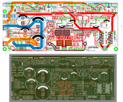
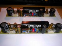
The basic schematic of the first version is bellow. The PCB is double sided and it is not really good for the thermo-transfer job, some of the ''hefty'' vias are unther the main caps, etc.
The board is uniwersal and BJT or mosfet OP tranies can be fitted on it. The IPS boards have 10pin connector (two pins for each net). Set of the protections and PSU is included.
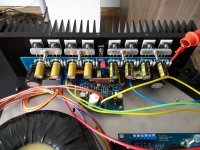
But at the moment I am working on a bit more advanced version. There is cap multipler (or rail stabilisation), mosfet relays, full protections including temperature and short circuit protectoin + EF3 with sanken OP tranies (mosfet version can be build on it too).
Lot of work and tests but hope before end of the year I will finish it up. First prototype passed test anyway.
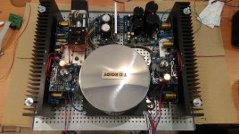
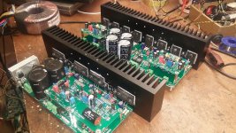
I decided to go with single par amplifier, there is no need to have more power than 50-80W at home (for me anyway). On the single board there is minimum wiring and minimum connections in between the modules, all is compact and focusse on the highest sound quality. Powerwise is will suit me in 100%.
On FB link bellow there are a few movies showing how it works.
Regards Peter
The board is uniwersal and BJT or mosfet OP tranies can be fitted on it. The IPS boards have 10pin connector (two pins for each net). Set of the protections and PSU is included.
But at the moment I am working on a bit more advanced version. There is cap multipler (or rail stabilisation), mosfet relays, full protections including temperature and short circuit protectoin + EF3 with sanken OP tranies (mosfet version can be build on it too).
Lot of work and tests but hope before end of the year I will finish it up. First prototype passed test anyway.
I decided to go with single par amplifier, there is no need to have more power than 50-80W at home (for me anyway). On the single board there is minimum wiring and minimum connections in between the modules, all is compact and focusse on the highest sound quality. Powerwise is will suit me in 100%.
On FB link bellow there are a few movies showing how it works.
Regards Peter
Attachments
Last edited:
Member
Joined 2009
Paid Member
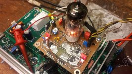
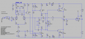
Inspired by Valery's hedphone preamplifier VAS I have made a quick board for a new hybrid. It needs a bit of the more work but It plays the music for a couple past days and does the job very well.
The new VAS system looks realy good. The only drawback is extra amount of heat
I like to spend some time on simple circuits, there is a lot of things that can be learned and a lot of fun.
I do not have MPSA/PZTA models so on the schematic there are 2N5401/5551 instead.
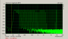
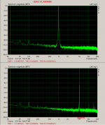
The measurements are taken form IPS board connected to standard EF3 OPS board.
Special THANKS to Vall
Regards
The new VAS system looks realy good. The only drawback is extra amount of heat
I like to spend some time on simple circuits, there is a lot of things that can be learned and a lot of fun.
I do not have MPSA/PZTA models so on the schematic there are 2N5401/5551 instead.
The measurements are taken form IPS board connected to standard EF3 OPS board.
Special THANKS to Vall
Regards
Attachments
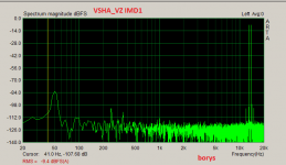
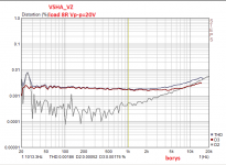

Today I have change circuit for standard CCS VAS and changed compensation so the square waves were looking nice.
I have tryed to make measurements at the same conditions. The IPS board was conneted at the same setup EF3 OPS. I will work further and post results.
I am not sure how to cancel the third harmonics in this kind of setup.
Regards.
I have tryed to make measurements at the same conditions. The IPS board was conneted at the same setup EF3 OPS. I will work further and post results.
I am not sure how to cancel the third harmonics in this kind of setup.
Regards.
Attachments
Today I have change circuit for standard CCS VAS and changed compensation so the square waves were looking nice.
I have tryed to make measurements at the same conditions. The IPS board was conneted at the same setup EF3 OPS. I will work further and post results.
I am not sure how to cancel the third harmonics in this kind of setup.
Regards.
Nice design!
WRT cancelling 3rd harmonics - it's very hard to do in reality even if sym
says you can. Always easy to cancel 2nd, just balance.
WRT Vas stage, I recommend trying a simple darlington voltage stage, both
P ch devices. The secret is you must ground the collector of 1st transistor
and not connect it to swinging VBE. This will allow more OLG and most likely
lower distortion - if that is your goal.
You can also try TMC compensation which will lower distortion even further.
I'm not sure how well TMC will work with the double BJT OP stage as IP BJT
of the CFP OP pair has significant capacitance. Generally a pre driver gets
best results. Once you have pre driver and TMC, as you can imagine the
OLG, especially at HF is very high and distortion numbers go super low.
However stability gets tricky and I'm not sure if it translates into better
sound subjectively.
As an example I am finishing a fully balanced CFB amp that has darlington
VAS and TMC with pre driver on OP stage aswell. You can get spice
distortion down to 0.000010% or so (even lower depending on comp) at
10kHz driving 200W 4 ohms but stability becomes tricky as does clipping
behaviour.
Interestingly I can also substitute a tube in front end and for the small
increase in distortion, stability is much better. The very low and benign
capacitances on tubes seem to make them great candidates for IP pair
driving very high OLG / fast amp.
Long live tubes!
Edit - just realised your latest design doesn't use CFP.
Terry
Last edited:
Today I have change circuit for standard CCS VAS and changed compensation so the square waves were looking nice.
I have tryed to make measurements at the same conditions. The IPS board was conneted at the same setup EF3 OPS. I will work further and post results.
I am not sure how to cancel the third harmonics in this kind of setup.
Regards.
Borys can you post the .asc file.
Thanks.
ashok
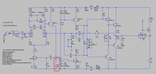
There You go, the as build file bellow. I had to make compenastion as in the file bellow, with other values the amp was under-compensated in the real life but it was perfect in the symulations. But I think I found the source of dominated H3.Tomorrow will test it for sure.
There You go, the as build file bellow. I had to make compenastion as in the file bellow, with other values the amp was under-compensated in the real life but it was perfect in the symulations. But I think I found the source of dominated H3.Tomorrow will test it for sure.
Attachments
Padamiecki
Yes it will give a more OLG but this is not good in this case, connection like this will upset the current mirror balance. To go this rute the current mirror must be replaced with resistors as in the Vallery's preamplifier.
I am trying to not exeed 50dB OLG, at the moment design has around 65dB.
Better way is to linearise than wind up the OLG (I hope this is good way).
zenelectro
Thanks for input !!
The measurements are not the no1 in the inportance list but it would be nice if they were good.
Maybe the better way is to focus a bit more about ''bomb proofnes'' of the amplifier and ''difficult'' load properties.
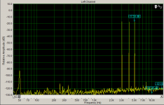
One of the forum members is measuring distortions but in IMHO better way, measurement is taken from the speaker so we have full influence of the amplifier regardless sound.
I must try to go this rute too.
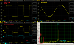
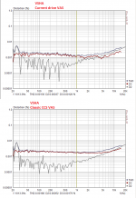
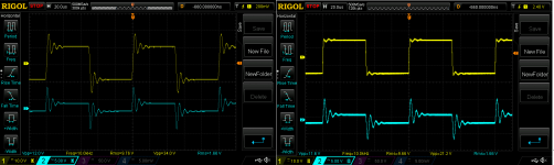
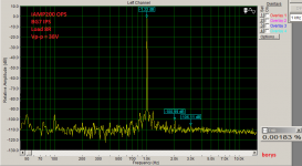
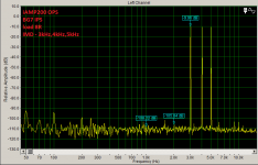
Bellow output voltage and current measurements of the both versions (standard ccs vas is on the right and current drive vas on the left). The measurements taken from 8R + 0,47uF in parallel as a capactive load.
The current driven VAS --> I didn't spent enough time to fine tune it but on the scope standard square waves tests were perfect.
Regards Peter
Yes it will give a more OLG but this is not good in this case, connection like this will upset the current mirror balance. To go this rute the current mirror must be replaced with resistors as in the Vallery's preamplifier.
I am trying to not exeed 50dB OLG, at the moment design has around 65dB.
Better way is to linearise than wind up the OLG (I hope this is good way).
zenelectro
Thanks for input !!
The measurements are not the no1 in the inportance list but it would be nice if they were good.
Maybe the better way is to focus a bit more about ''bomb proofnes'' of the amplifier and ''difficult'' load properties.
One of the forum members is measuring distortions but in IMHO better way, measurement is taken from the speaker so we have full influence of the amplifier regardless sound.
I must try to go this rute too.
Bellow output voltage and current measurements of the both versions (standard ccs vas is on the right and current drive vas on the left). The measurements taken from 8R + 0,47uF in parallel as a capactive load.
The current driven VAS --> I didn't spent enough time to fine tune it but on the scope standard square waves tests were perfect.
Regards Peter
Attachments
Last edited:
Padamiecki
Yes it will give a more OLG but this is not good in this case, connection like this will upset the current mirror balance. To go this rute the current mirror must be replaced with resistors as in the Vallery's preamplifier.
I am trying to not exeed 50dB OLG, at the moment design has around 65dB.
Better way is to linearise than wind up the OLG (I hope this is good way).
IME this approach (linearise) only works is to a degree for the following
reasons:
Most of the distortion happens in the OP stage and a lot of that distortion is
complex high order distortion from OP device switching.
Once the miller cap kicks in with it's load on the VAS, that load becomes in
itself very non linear because the VAS voltage swing is compensating for
those OP stage non linearities.
TMC really does a good job of keeping this higher order distortion down.
Having said this I haven't got a good handle on what TMC actually sounds
like. I'll be having a play with this shortly.
cheers
Terry
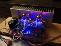
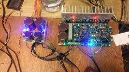
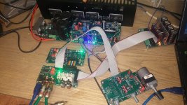
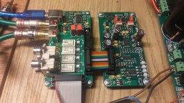
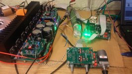
A few more toys
Complete system including modular preamp and selector with DAC.
My sound card is not sufficient to measure the system anymore, time to get a new one..
Regards
Complete system including modular preamp and selector with DAC.
My sound card is not sufficient to measure the system anymore, time to get a new one..
Regards
Attachments
.....
My sound card is not sufficient to measure the system anymore........
What sound card are you using currently ?
A few more toys
Complete system including modular preamp and selector with DAC.
My sound card is not sufficient to measure the system anymore, time to get a new one..
Regards
Great stuff
 Both design- and build-wise.
ahok
I have emu0204 with two ak4396 on the board.
I like it but the worst thing is the drivers, creative make a joke of it. Long story to set it up on win7. That is the second reason to change sound card.
Val
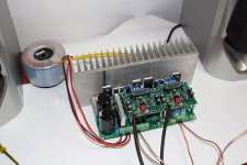
Thanks a lot, I am working very hard day and night No time for a break. The complete amp must be finished this year, I have no amp at home yet .
Next step is bluetooth DAC so my wife can play music directly from the phone.
Regards
I have emu0204 with two ak4396 on the board.
I like it but the worst thing is the drivers, creative make a joke of it. Long story to set it up on win7. That is the second reason to change sound card.
Val
Thanks a lot, I am working very hard day and night
No time for a break. The complete amp must be finished this year, I have no amp at home yet .Next step is bluetooth DAC so my wife can play music directly from the phone.
Regards
- Status
- This old topic is closed. If you want to reopen this topic, contact a moderator using the "Report Post" button.
- Home
- Amplifiers
- Solid State
- Very Simple Hybrid Ampifier