Franz G said:
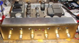
I MUST show you my christmas holiday project for this year: Renovation of a Scott Stereomaster 299, found in the garbage (!) on last friday
Franz
OMG! The layout of that thing looks fantastic! And there are people that throw this away!!! Nice gift for you!
I just got an audioquest cable in my mail, not nealy as cool as that amp!
I still have to finish the case for the power supply. I will do that tuesday...
Have a good time all!
Still looks quite shiny for something that's pulled out of the garbage.
This foto is showing the amp before cleaning. Not too bad!
It was in the wooden enclosure, in quite good condition.
BTW: the knobs are made from massive aluminium.
Franz
Attachments
Hanzwillem said:OMG! The layout of that thing looks fantastic! And there are people that throw this away!!! Nice gift for you!
Those are really nice (don't know how they soind stock, but good iron & chassis (a bit small thou). We took one (not exactly the same model, LK48 kit verision) and turned it into a nice little power amp (the remaining knobs & faceplate paid back a 1/3 of the original purchase cost)
That is a real nice Xmas present Franz...
dave
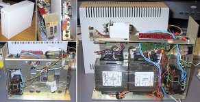
Last night i had a creative session and scrounged up power supply & heatsinks for my VBIGC project. The powersupply is a bit further along then the amp...
I got around the relay/timer problem in a retro way... with a HT trafo donated from one Euro R-R and a bracket, socket, and EZ81 from another. LT trafos (1 for each rail) are from older version of Apple Imagewriter II printer, AC filter from the same source (i'll be running close to the max voltage wize). Rectifier board from a BGT kit, the lovely all aluminum case used to house a 30MB HD.
dave
Attachments
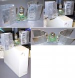
The amp still needs a donor, for the body... with the strict width size i may have to get creative, but i cobbled something togther to represent what i'm going for... with Franz already making smallest, i went with a look that is kinda different.
I've got the valve board in the picture, but won't use it (besides loosing 9 solder joints by turfing it, drilling out the holes to fit the socket left no pads to solder to and is toast now anyway -- digi note that for the next rev)
Heatsink donors were 4 dead Monsoom MH350 amps.
dave
I've got the valve board in the picture, but won't use it (besides loosing 9 solder joints by turfing it, drilling out the holes to fit the socket left no pads to solder to and is toast now anyway -- digi note that for the next rev)
Heatsink donors were 4 dead Monsoom MH350 amps.
dave
Attachments
I got around the relay/timer problem in a retro way... with a HT trafo donated from one Euro R-R and a bracket, socket, and EZ81 from another.
When I understand you correct, this will result in a slow power up for the tube buffer, isn't it?
But what you need is a delay for the power stage, for the LM3875, otherwise you will have full DC at the output during start up of the tube buffer!
Very interesting design, Dave!
Franz
Franz G said:[When I understand you correct, this will result in a slow power up for the tube buffer, isn't it?
Yes...
But what you need is a delay for the power stage, for the LM3875, otherwise you will have full DC at the output during start up of the tube buffer!
Why... it should look just like a regular GC to the speakers, shouldn't it? Joe doesn't have a delay on his.
(Even thou i drew the schematic -- i alway had in the back of my mind that the delay was for the HT where it is needed, but instead it is on the LT which now has me confused....)
dave
planet10 said:Joe doesn't have a delay on his.
Dave, Joe left the valve permanently powered on (!), and he must had some sequence to power the amp on when disconnected from mains, like a manual switch on the speaker outputs.
carlosfm said:valve permanently powered on
thanx for reminding me to do that. I still don't see where the DC on the GC outputs comes from?
dave
Fellow builders
I put together a small pdf document that covers most of the errors with the PCB's. These were pointed out by other builders and myself. This document is to help you guys to bring this project to a good end. It is by no means disrespectful to both Franz and Zang as I already stated in a previous post.
If any of you have suggestions or comments about the document please let me know, I'm also only human.
Because the document is to big in size I'm not able to post it here. For those who want a copy, let me know and I will mail it to you.
Best regards
I still don't see where the DC on the GC outputs comes from?
The question is, what is the voltage at the cathode eg. the input of the LM3875 while starting up.
With a solid state HV-psu, there is a transient from the HV negative voltage to 0 V within a few seconds. And this transient is amplified and appears as DC at the output.
While writing this, I think, your solution could work: If in your solution the voltage at the cathode will always be 0V, then it will be O.K.
May I suggest, that you attach some 8 ohm resistors and a multimeter instead of speakers, while turning on the first time?
Anyway, should your configuration work without delay circuit, then you will have the same effect, when you disconnect the power for some seconds and the rectifier is still conducting!
BTW: Joe is not using a cathode follower in his circuit, so maybe in his circuit is no startup transient at the chips input.
Franz
Franz G said:With a solid state HV-psu, there is a transient from the HV negative voltage to 0 V within a few seconds. And this transient is amplified and appears as DC at the output.
While writing this, I think, your solution could work: If in your solution the voltage at the cathode will always be 0V, then it will be O.K.
May I suggest, that you attach some 8 ohm resistors and a multimeter instead of speakers, while turning on the first time?
Good idea... i have some nice finned 25 W jobbies just for that
BTW: Joe is not using a cathode follower in his circuit, so maybe in his circuit is no startup transient at the chips input.
???
Back to the movie... Scrooged
Merry HoHo.
dave
Franz G said:Joe himself does NOT use a cathode follower in his amps. Hi just suggest this for the DIY version.
I'm pretty sure he does use a CF... gussied up to the max, based on the FVP, but still a CF.
An externally hosted image should be here but it was not working when we last tested it.
dave
Only a little bit hum, but on the 92dB speakers not really a problem.
Hans-Willem
Please check, if there is a ground connection between the tube ground and the ground of the high current part of the psu.
Maybe this is missing in the documentation: add a bridge wire in the psu, from the high voltage ground to the high current ground, as shown in the attached picture.
Franz
Attachments
OK guys, I split up the guide in four different pages so I'm able to post the darn thing here. If any of you have comments or remarks, just let me know. I hope this guide will help those who had second thoughts about this little project.
Here come's page 1
Regards
Here come's page 1
Regards
Attachments
- Status
- This old topic is closed. If you want to reopen this topic, contact a moderator using the "Report Post" button.
- Home
- Amplifiers
- Chip Amps
- VBITNGC building & comment