My suggestions for the Rev2 board.
The space for the capacitors in the HT section have to accomodate 100V types.
Numbering of the capacitors in the HT section must start from C21 through C26.
Foresee more clearance between C22 and C23 (old numbering) because they are at least 16mm dia. with a 7,5mm pitch
Foresee a 5 and 7,5mm pitch for C24 and C25 (old numbering)
C18 in the heater section is a 4700µF/16V type. All the capacitors I could find are at least 16mm in diameter. This is hard to fit at the present board.
Rearange the fuseholder and 45VAC entry on the board to give more clearance for the diodes.
In the high current section the option of using 50V capacitors. This means for C9 and C10 a diameter of 30,5mm with a pitch of 10mm.
Lose the silly 9 pin connector. By doing this you can give bigger solder pads on the output of the high current section so that a bigger wire can be used. It will also be easier to place a bridge between the ground planes of the high and low current section.
My 2 cents
P.S. This is not criticism, just some ideas to improve the Rev2 board
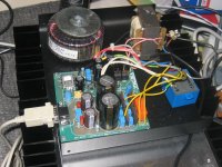
A picture of my fully operational power supply...
The ground wire between HV and HC GNDs helped, but it is not silent as my alephs yet. But good enough anywayz. The supply is not optimal yet as you can see, I do not think my insurance will cover this thing")
Anywho, I hope the workshop will re-open soon
The ground wire between HV and HC GNDs helped, but it is not silent as my alephs yet. But good enough anywayz. The supply is not optimal yet as you can see, I do not think my insurance will cover this thing
Anywho, I hope the workshop will re-open soon
Attachments
Mayby in the next revision of the PCB you can add text on the outputholes in the ampPCB (Signal and gnd).
I do not use the sub D connector. Can i just connect pin 3 to pin 1 on the PSU PCB?
Can i use the big holes for tube HV (+, - and gnd) on the edge of the PSU PCB and not the small solderpads of the sub D connector holes? The big holes on the edge of the PCB are way easyer and bigger.
Nice Photo of your PSU PCB Hanzwillem, looks good. Is that small heatsink for the 317 regulator enough?
Wim
Good idea
Sure, why not
Yes you can. I will be doing the same because I'm not using the 9pin connector either.
Regards
Mayby in the next revision of the PCB you can add text on the outputholes in the ampPCB (Signal and gnd).
Good idea
I do not use the sub D connector. Can i just connect pin 3 to pin 1 on the PSU PCB?
Sure, why not
Can i use the big holes for tube HV (+, - and gnd) on the edge of the PSU PCB and not the small solderpads of the sub D connector holes? The big holes on the edge of the PCB are way easyer and bigger.
Yes you can. I will be doing the same because I'm not using the 9pin connector either.
Regards
For the next revision of the PCB it seems practical to number all the input- and outputholes of the three PCB's. Equal numbers have to be connected.
I do not think many builders place the potmeter onboard, but hardwire this device, because off the configuration of the enclosure or heatsinks. So this makes the PCB easyer and the inputsholes (from a source) can be moved from the amp PCB to the tube PCB. Makes it a lot easyer i.m.o.
This is no critic, only subjects to discuss.
A good discussion makes a better design.
I will sure buy the next revision PCB-set.
Can i just connect pin 3 to pin 1 on the PSU PCB?
No, don't do it this way! When you disconnect the amp from the psu and connect again, then you will not have any delay.
Franz
No, don't do it this way! When you disconnect the amp from the psu and connect again, then you will not have any delay.
Why should one always disconnect the power supply from the amplifier? I'm not saying that it's not a good safety feature but,... wel you know what I mean.
Regards
I do not ever disconnect the PSU from the amp (i make a permanent connection). I make one 2-pole switch to give power on all trafo's (3x) and because of the relais/555 timer i get after a few seconds power on the amp.
Or is this not good?
Maybey i make the PSU PCB in the same enclosure of the amp add tube PCB. I am not going for as little as possible.
Or is this not good?
Maybey i make the PSU PCB in the same enclosure of the amp add tube PCB. I am not going for as little as possible.
wim said:For the next revision of the PCB it seems practical to number all the input- and outputholes of the three PCB's. Equal numbers have to be connected.
I do not think many builders place the potmeter onboard, but hardwire this device, because off the configuration of the enclosure or heatsinks. So this makes the PCB easyer and the inputsholes (from a source) can be moved from the amp PCB to the tube PCB. Makes it a lot easyer i.m.o.
Yeah,THANKS!I have conscious of this case.I am going to make a combine amp pcb.
Zang
digi01 said:Yeah,THANKS!I have conscious of this case.I am going to make a combine amp pcb.
Zang
Well the "original concept" was a small(tiny) tube buffered amp.
That concept was good, but the execution was slightly flawed / bugged.
I personnaly was going to build this to use on my desk @ work so size does matter.
If your going to break away from the tiny concept, it is my SUGGESTION that the amp be designed for a generic enclosure. Something that everyone has access to such as the Hammond boxes.
And I would still like to build one for my desk.
I think it depends on the pot and coupling caps how big the enclosure is going to be...
I really wanted to use the paper in oil caps, also I had some Jensen and Bosch MP, but they are even larger! I have the opinion that the coupling cap as well as the tube used influences the sound. I opted for best sound and not size, which meant the case of 42x100x160mm was about as small as it could get... I could have squeezed it into a smalled enclosure, but I do not like the looks of the smaller ready made enclosures that were easily available
I really wanted to use the paper in oil caps, also I had some Jensen and Bosch MP, but they are even larger! I have the opinion that the coupling cap as well as the tube used influences the sound. I opted for best sound and not size, which meant the case of 42x100x160mm was about as small as it could get... I could have squeezed it into a smalled enclosure, but I do not like the looks of the smaller ready made enclosures that were easily available
Yes Hanzwillem, i agree that i go for quality and not as little as possible.
Eorocardformat (100X1560 mm) seems perfect and there are nice aluminium cases (Conrad) in this format witch are maximum about 100 mm high. That must be enough for bigsieze (quality) caps, a big potmeter and heavy in- and output terminals.
PSU can be made in the same kind but lower enclosure as the enclosure of the amp (55 or 80 mm high).
How about?
Look on www.conrad.nl artikelnumbers 522970-02, 522945-02 and 522953-02. Just as example. RScomonents has also nice aluminium enclosures.
wim said:How about?
Look on www.conrad.nl artikelnumbers 522970-02, 522945-02 and 522953-02. Just as example. RScomonents has also nice aluminium enclosures. [/B]
I used those cases a lot. Most of the time they are big anough and the quality is just perfect. For this project though, to fit the 120x120mm PSU PCB and three trafo's I used part nr. 520446. Just pick the one where the big cans will fit inside, they come in lots of sizes
- Status
- This old topic is closed. If you want to reopen this topic, contact a moderator using the "Report Post" button.
- Home
- Amplifiers
- Chip Amps
- VBITNGC building & comment