GeWa said:
Which coupling cap (1µF) did u used? I have some Angela MKP 630V types that I want to try. (small size)
Cheers
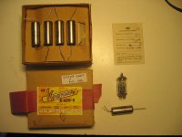
I used these russian caps. I had also four of 1uF. Two of them are now in the amp, and the other two will go in my speakers.
I also used these in my BoZ, which improved a lot over the Wima MKPs that were installed first.
Attachments
Hi guys
For some reason my relay doesn't work with the delay circuit. If I apply a voltage on the relay's coil it works, so the relay isn't the culprit. No load voltage is 10,12VDC. I have a 250K trimmer + a 220K resistor.
The regulator circuit for the heater supply works fine.
Any ideas? For now I want to wish all of you a Merry Christmas


For some reason my relay doesn't work with the delay circuit.
If I apply a voltage on the relay's coil it works, so the relay isn't the culprit. No load voltage is 10,12VDC. I have a 250K trimmer + a 220K resistor.The regulator circuit for the heater supply works fine.
Any ideas? For now I want to wish all of you a Merry Christmas
You do know you have to short two pins of of the D-sub cable for the relay to close don't you? I take you made the modifications digi pointed out earlier.
See http://www.diyaudio.com/forums/showthread.php?postid=752960#post752960
Good luck!
See http://www.diyaudio.com/forums/showthread.php?postid=752960#post752960
Good luck!
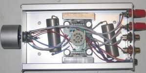
Looks good inside Hanzwillem; I assume that the heatsinks of the LM3875 are connected to the enclosure? Otherwise i am not sure you have enough heatsingarea for long and loud playing music with the amp.
I see that you do not use shielded wires for the inputs (to the potmeter, and from the pometer to the amp). Maybey that is the reason for hum?
Onother question: is there a schematic fo the pintout from the sub-D? a schematic that shows also the connection from pin 1 and 3?
Happy christmas and a good (hobby)newyear!
You do know you have to short two pins of of the D-sub cable for the relay to close don't you?
Euhh......I forgot that one.

Just bridged pin 1 and 3 but no luck either. Maybe it's the NE555 that's gone south.
Regards
Maybe it's the NE555 that's gone south.
No, I dont think. They are very robust.
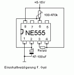
Let's try to find the problem, look at the simple circuit below:
- is the orientation of the NE555 correct (not as printed as on the silk side)?
- Voltage between pin1 and 8 of the NE555 correct?
- some Voltage between pin 1 and 6 of the NE555?
- and the voltage between pin 3 and 4 of the NE555, after 20 sec?
BTW: The idea from the bridge between pin 1 and 3 of the d-sub connector is to reactivate the delay, as soon as the amp is disconnected.
So, if you use two d-sub connectors (the amp from Hanz-Willem), one at the psu and one at the amp, place this bridge inside the amp between pins 1 and 3!
Franz
Attachments
Here you find a foto from this famous bridge between pin 1 and 3:
http://www.diyaudio.com/forums/showthread.php?postid=752960#post752960
Franz
http://www.diyaudio.com/forums/showthread.php?postid=752960#post752960
Franz
I see that you do not use shielded wires for the inputs (to the potmeter, and from the pometer to the amp). Maybey that is the reason for hum?
Hardly, as there is no AC in the amp's box. It must be a grounding issue.
Franz
Franz
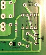
I am trying to figure out how this delay circuit is connected. According to your drawing and the wiring diagram of the power supply the 47µF capacitor is connected between GND and pin 2 of the timer IC. On the PCB this capacitor goes from GND in series with the resistor and trimmer. Also the resistor (trimmer) is on one side connected to the +VDC, I can't see that on the PCB. Am I totally missing the point here or is there something wrong with the PCB. The thing that strikes me the most is that Hanzwillem has a working amp, we all have the same PCB's do we?
Regards
Attachments
Fellow builders
I just cut the trace on the PCB and made the two additional connections, as shown in the image of my previous post, and now the time delay works. At about 27 seconds after switching On the power the relay activates. And now it's time to go to bed!
Cheers
I just cut the trace on the PCB and made the two additional connections, as shown in the image of my previous post, and now the time delay works. At about 27 seconds after switching On the power the relay activates. And now it's time to go to bed!
Cheers
Very sstrange that Hanzwillems amp is working without the fix you named GeWa.
Maybe hanzwillem can tell us how he did it, and mayby he is willing to make some detailed pictures of all the PCB's he made?
As i asked before, it shout be nice if there was a COMPLETE assume of bugs and fixes.
I do not work any further on this amp without such a summary. It it laying in my junkbox at the moment. I think that others think the same.
As i asked before, it shout be nice if there was a COMPLETE assume of bugs and fixes.
I am very sorry, but I cannot help you. Someone who assembled it successfully with all three boards from Zang could do it.
It was not always easy for me, to keep track but I never wanted a question a long time beeing unanswered.
Franz
I build it exactly as in this post:
http://www.diyaudio.com/forums/showthread.php?postid=767836#post767836
a 470k resistor gave plenty of time to stabilize.
the only error on the two amp boards is the reversed tube socket. Just solder it on the other side and the amp can be completed.
I thought my post earlier (
http://www.diyaudio.com/forums/showthread.php?postid=790426#post790426 ) was pretty clear.
The silkscreen for the high current diodes only is wrong. Just use common sense and mount all diodes in the same and propper direction. I am not at home at the moment, so I cannot post a picture.
It is all not as bad as it seems.
Do use a small sink for the LM317 by the way. You could do without, depending on the input voltage of course, but the IC will get really hot and may cause problems in the long run.
Here I am again.
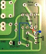
The picture in the post that Hanzwillem is reffering to states that the PCB layout of the timer circuit is indeed wrong. If you put a resistor (470K) on the PCB with the small bridge (red circle) everything works. Zang should have been a bit more clearly what he did and why he did it this way. If you populate the board with the trimmer and the resistor you have to follow the changes I made.
If one follows the traces on the PCB and compare them with the wiring diagram it shows what is wrong with the timer circuit. If somebody knows how to put up a wiki page I will post all the changes that have to be made to get a good working amp.
Wel, this is one of those projects where "Murphy's Law" is getting the upper hand. I can understand that some people are getting frustrated because of all the minor mistakes. I don't point a finger to Franz or Zang, you can check something over and over until you're blue in the face and still have screw ups. 😉
Merry Christmas
Regards
Attachments
Wel, this is one of those projects where "Murphy's Law" is getting the upper hand. I can understand that some people are getting frustrated because of all the minor mistakes. I don't point a finger to Franz or Zang, you can check something over and over until you're blue in the face and still have screw ups.
Thank you!
I MUST show you my christmas holiday project for this year: Renovation of a Scott Stereomaster 299, found in the garbage (!) on last friday 😀 😀 😀
Merry christmas!
Franz
Attachments


- Status
- Not open for further replies.
- Home
- Amplifiers
- Chip Amps
- VBITNGC building & comment