GeWa said:
What kind of potmeter are you using for this amp?
I am going to use a very old carbon potmeter from Ruwido. I had it laying around and now it finally will get a use. It is a huge one, barely fits the amp enclosure. I thought I had my camera here, but apperently not. Pictures will come later...
It seams my tube also has a direct connection between pin 5 and 6, thus anode 2 and +heater are connected together, I think we have to disconnect the other heater from ground then, that'll solve it I think.
But right now I am a little short in time, so do not hassle into things just yet")
But right now I am a little short in time, so do not hassle into things just yet
I don't think it is a matter of disconnecting one pin.
The pinout given in the datasheets is from below (looking at the pins) but here is interpreted as from above. The solution for this is to mount the socket on the component side.
I was disappointed because I had a hard time fitting the socket just to find that it couldn't work as-is....
Cheers
Andrea
Attachments
Andypairo said:The solution for this is to mount the socket on the component side.
Indeed. I made the same mistake with my 1st tube PCB (handdrawn ARC SP3A pre-amp clone).
I just did a bit of PhotoShop/Illustrator to get the following 2 illustrations.... the one in this post is with the tube socket mounted on the silkscreen side (as intended but wrong -- digi don't add power to your board) and in the next post, mounting socket on the solder side (a but tricky to solder but probably doable -- I may have to use my isosocket).
dave
Attachments
planet10 said:
Indeed. I made the same mistake with my 1st tube PCB (handdrawn ARC SP3A pre-amp clone).
Did that preamp work well?
planet10 said:
(as intended but wrong -- digi don't add power to your board)
dave
In this case fireworks might happen


I suggest the use of a "spare" tube for the first tests.
Cheers
Andrea
Re: Boards?
I got mine nov 11. sent on oct 25. Maybe everyone can update the wiki when or if they got their boards?
http://www.diyaudio.com/wiki/index.php?VBITNGC
Yesterday I got my tranny for the tube supply and also some very very nice rusian military grade coupling capacitors. So I'll be finishing this project this week
evo said:Hi all,
Just wondering if everyone's got their boards yet?
WIKI says mine were sent Oct 27th, i'm in the UK
I got mine nov 11. sent on oct 25. Maybe everyone can update the wiki when or if they got their boards?
http://www.diyaudio.com/wiki/index.php?VBITNGC
Yesterday I got my tranny for the tube supply and also some very very nice rusian military grade coupling capacitors. So I'll be finishing this project this week
planet10 said:
I just did a bit of PhotoShop/Illustrator to get the following 2 illustrations.... the one in this post is with the tube socket mounted on the silkscreen side (as intended but wrong -- digi don't add power to your board) and in the next post, mounting socket on the solder side (a but tricky to solder but probably doable -- I may have to use my isosocket).
dave
It seemed that also I got confused with how you look at the pins, from the bottom or from the top... It is not the first time that that happened to me
What a shame, I am really sorry about that mess! And it is at least 50% my fault.
It's true: the upper board is mirrored, so has to be assembled from the cupper side.
And this seems true also: there is some mess nearby the NE555 with the delay circuit.
It like this: I have 10 amp boards from Zang, but never tried one, as I assembled two amps, but based on my prototype boards.
And I did not order or assemble the finished psu boards from Zang up to now.
Franz
Re: Boards?
Mine came today-thanks
evo
evo said:Hi all,
Just wondering if everyone's got their boards yet?
WIKI says mine were sent Oct 27th, i'm in the UK
Mine came today-thanks
evo
How is everybody doing with their projects?
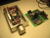
I am approaching the finish. The amp itself is almost finished. I got all the parts for the PSU as well. I will start building assambling that later this week, or maybe even tomorrow.
All signal wiring is silver. PSU wiring is salvaged from some sony ES DAT recorder, as well as the ALPS pot.
Decoupling caps are military grade russian paper in oil. Very nice stuff.
I hope to be able to finish this one soon!
Attachments
Hallo Hanzwillem,
Very, very nice construction on the photo ! Is it a conrad enclosure you build it in? It looks great!
Did you read and repair all the reported missngs in the PCB's?
Can your please post all the chanches that you made on the original schematics and PCB's, i am sure you help many builders (me included).
I stop with the project becouse off all the bugs in the PCB's, and i am not a crack you know. So i wait till anyone has a working prototye of it.
I agree with Wim, not starting mine yet for the same reasons.
Yes, it is a case from Conrad. Part.nr. 523232 It is only 10,95 Euro. And looks pretty good. I drilled a hole in the top plate were the tube will stick out.
I guess it will be my duty to be one of the first to fire one of these babies up
I have not really made a list of problems occured, the biggest ones were ones already described. Of course I do not know if the thing will work, but my guess is that it will work. We'll see...
Also, please do not forget to mount the T-network on the bottom of the amp board. Easy to forget that part
By the way. Were did mr. digi go? I hope he didn't get hurt by an exploding tube
- Status
- This old topic is closed. If you want to reopen this topic, contact a moderator using the "Report Post" button.
- Home
- Amplifiers
- Chip Amps
- VBITNGC building & comment