wim said:i do not understand your point. A simple and common low current trafo of 20-0-20 VAC is good for the job, with both windings in serie. What you get is 2*20VAC = 40VAC, fine in the range Franz told us.
I can tell you what i'm doing.... it doesn't relate to the circuit board thou. I wanted to use parts i have on hand, and i wanted to avoid the doubler circuit. I have quite a few 120V to 120V 20 VA (170mA) trafos. I am going to take 2 and stack them with the primaries wired in series and the secondaries in series. This will give me a nominal 60-0-60 VAC trafo that will be stressed very little by the load on it. These trafos usually sell at garage sales & thrift stores for $1-2.
dave
i wanted to avoid the doubler circuit
Why? Please be aware, that the voltage doubler is absolutely no disadvantage in this application!
It is an elegant circuit, used by many highfi manufacturer (for example Fisher) for tube preamps (to deliver a few mA).
And it allows the use of easily available trannies.
Don't expect the amp to sound better without voltage doubler.
When you want to do something better (tweak?) and have enough space in the amps enclosure, you could add two bypass caps to ground nearby the tube: one at the anode, the other on the base of the cathode resistor. Every value >10uF should be O.K.
Franz
Yes Wim
I hoped for some answer from Zang.
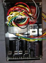
The best: I post a foto from a prototype. The correct orientation of the MUR diodes on your board is the same.
BTW: This foto is just showing a layout study of the psu, including two trannies at this time.
Franz
/Edit: the example is wrong! Look at the big caps: this prototype board has different polarisation than Zang's board! So, the correct orientation would be 180 degrees turned to this foto with the boards from the group buy!
I hoped for some answer from Zang.
The best: I post a foto from a prototype. The correct orientation of the MUR diodes on your board is the same.
BTW: This foto is just showing a layout study of the psu, including two trannies at this time.
Franz
/Edit: the example is wrong! Look at the big caps: this prototype board has different polarisation than Zang's board! So, the correct orientation would be 180 degrees turned to this foto with the boards from the group buy!
Attachments
Exactly, Per!
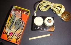
I cannot answer you, why I was always attracted by very small electronic gadgets
In the meantime, I started to solder smd parts (!!!), PCM2706 was the first step.
BTW: did you know the smallest radio out of the mid 60ies? Here a foto of mine and a link http://www.radiomuseum.org/r/amsa_micro.html
Regards
Franz
Attachments
I got a box from Zang today!.... I got a box from Zang today!....
Zang, can you see me dancing?
I opened the box and now have my PCB’s for this amp.
I then went in search to the original thread to review when I found this one.
I quickly parsed this thread and pulled out the important info and put into the attached doc.
Maybe a build Wiki would be better. But my doc is a starter for anyone looking for the "starting point" in construction.
I have some FREE heat sinks that would compliment this project nicely for anyone who wants to pay shipping only.
I will post a picture in the next day or two.
The points I see remaining to review BEFORE construction follow:
1. Diode orientation.. Do we have a final answer?
2. Heater supply = 6.3 & 0(grd) correct?
3. Final count of voltages required for the "official" Franz / Zang version?
4. Tube socket mounting hole needs to be drilled out larger?
5. Any other silk screen inaccuracies that need to be noted before assembly?
After all this IS diy, and part of the fun is the challenge of getting it working.")
Franz and Zang- Thanks again for the hard work on this so far... Now let’s get the facts straight and inline so everyone can build one of these.
I foresee one on every desktop in every office so the world can enjoy good sound while pounding on the key board.
EDIT:
Ok, it says my zipped word doc is too large...
Email direct if you want a copy, but it is literally just the important specs and pics from this thread thus far...
Zang, can you see me dancing?
I opened the box and now have my PCB’s for this amp.
I then went in search to the original thread to review when I found this one.
I quickly parsed this thread and pulled out the important info and put into the attached doc.
Maybe a build Wiki would be better. But my doc is a starter for anyone looking for the "starting point" in construction.
I have some FREE heat sinks that would compliment this project nicely for anyone who wants to pay shipping only.
I will post a picture in the next day or two.
The points I see remaining to review BEFORE construction follow:
1. Diode orientation.. Do we have a final answer?
2. Heater supply = 6.3 & 0(grd) correct?
3. Final count of voltages required for the "official" Franz / Zang version?
4. Tube socket mounting hole needs to be drilled out larger?
5. Any other silk screen inaccuracies that need to be noted before assembly?
After all this IS diy, and part of the fun is the challenge of getting it working.
Franz and Zang- Thanks again for the hard work on this so far... Now let’s get the facts straight and inline so everyone can build one of these.
I foresee one on every desktop in every office so the world can enjoy good sound while pounding on the key board.
EDIT:
Ok, it says my zipped word doc is too large...
Email direct if you want a copy, but it is literally just the important specs and pics from this thread thus far...
Franz G said:Why? Please be aware, that the voltage doubler is absolutely no disadvantage in this application!
I have no personal opinion on using a doubler -- i've not been in a position to use one yet.
i started collecting parts for Joe's amp long before this (lovely & elegant) board set came along. The trafos cost $2 CAD and also allow me to easily get 150-0-150 VDC if i add a super-reg.
Supplies for the 3875 is undecided (but i have at least 4 or 5 choices in my junk box... it will depend somewhat on the chassis that comes along for this.
dave
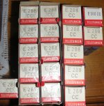
E288cc
Nice ingredient for this amp (look foto)
I will sell most of this tubes, but I am looking for a fair price. Here the first pair:
http://cgi.ebay.ch/ws/eBayISAPI.dll?ViewItem&item=6227141057
Franz
Nice ingredient for this amp (look foto)
I will sell most of this tubes, but I am looking for a fair price. Here the first pair:
http://cgi.ebay.ch/ws/eBayISAPI.dll?ViewItem&item=6227141057
Franz
Attachments
Troy
could you please mail me your word docu? I will review it and include the promised grounding scheme.
I can strongly recommend you to build as next project some USB-DAC, based on PCM2706 and probably a fine DAC-chip. Then copy the cd's with Excact Audio Copy to the harddisk, install ASIO4all and play the music with foobar...
You will be surprised, about the sound quality!
Kind regards
Franz
could you please mail me your word docu? I will review it and include the promised grounding scheme.
I foresee one on every desktop in every office so the world can enjoy good sound while pounding on the key board.
I can strongly recommend you to build as next project
some USB-DAC, based on PCM2706 and probably a fine DAC-chip. Then copy the cd's with Excact Audio Copy to the harddisk, install ASIO4all and play the music with foobar...You will be surprised, about the sound quality!
Kind regards
Franz
I can strongly recommend you to build as next project some USB-DAC
Any preference on which one Franz?
Franz G said:Troy
could you please mail me your word docu? I will review it and include the promised grounding scheme.
I can strongly recommend you to build as next project
You will be surprised, about the sound quality!
Kind regards
Franz
Will have to wait until next week as this is a new work PC and I have not migrated files from old to it yet.
As for USB-DAC... Next GB project? Wavelength Audio just did one and it is tube driven... I'm in for a DIY version!!! Actually 2-3 (home, office, friends)..
Any preference on which one Franz?
Based on PCM2706 or PCM2707. NOT Bus powered of course.
When you want to use your dac chip of choice, driven by I2S, here the simplest circuit:
http://www.diyhifi.org/forums/viewtopic.php?p=6018#6018
A more simple circuit, using the internal DAC is showed in the datasheet as example on page 28, figure 32. But the better choice is using the self powered version on page 29, figure 33.
PCM2706/2707 datasheet
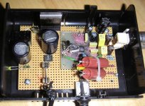
The picture is showing my first USB Dac.
BTW: in the last weeks, the vinyl virus got back to me. But sometimes I really prefer the musicserver and a playlist with direct access to all titles.
Franz
/Edit: sorry, getting more and more offtopic. This topic has good threads in the digital forum from diyaudio. Let's go back to the original topic.
Attachments
Further errors revealed
While assemblimg my amps I found the following annoying errors:
- The delay circuit, apart from the wrong orientation of the NE555, doesn't work as-is because there is nothing that charges the 47uF capacitor. You have to solder a resistor under the board to do so.
-Worst of all the filament pins are wrong... I get continuity with a tube in the socket between the +6.3V pad and.. the +60V one!!!

Something here's certainly out for lunch. I suspect a mirrored pinout.. but the question is: before selling a number of boards did Zang or Franz actually test them??
Please advise....
Andrea
While assemblimg my amps I found the following annoying errors:
- The delay circuit, apart from the wrong orientation of the NE555, doesn't work as-is because there is nothing that charges the 47uF capacitor. You have to solder a resistor under the board to do so.
-Worst of all the filament pins are wrong... I get continuity with a tube in the socket between the +6.3V pad and.. the +60V one!!!
Something here's certainly out for lunch. I suspect a mirrored pinout.. but the question is: before selling a number of boards did Zang or Franz actually test them??
Please advise....
Andrea
Re: Further errors revealed
I don't really see why that is. If I follow the traces I see that the filament is on pin 4 and 5 (also connected to GND and pin 9 for the screen) And the +60V for the anode to pin 1 and 6 for the two triodes.
As far as I can see this looks correct. But I haven't up and running yet, I am still missing the two LMs and also a trafo for the anode/cathode supply...
Andypairo said:-Worst of all the filament pins are wrong... I get continuity with a tube in the socket between the +6.3V pad and.. the +60V one!!!
I don't really see why that is. If I follow the traces I see that the filament is on pin 4 and 5 (also connected to GND and pin 9 for the screen) And the +60V for the anode to pin 1 and 6 for the two triodes.
As far as I can see this looks correct. But I haven't up and running yet, I am still missing the two LMs and also a trafo for the anode/cathode supply...
- Status
- This old topic is closed. If you want to reopen this topic, contact a moderator using the "Report Post" button.
- Home
- Amplifiers
- Chip Amps
- VBITNGC building & comment