Nah, how about "Distortionatrix"?
(For whipping those harmonics into shape!)
It's a good idea to localize the name, according to certain culture traditions. What's Zulu for Hamonizer?
")
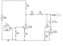
How does it work? The cathodes are tied together. With R1 wiper at ground we have nearly a diff amp except for the 33K resistor R7 (and C2/R3). With R1 wiper at max signal we have 2 tubes almost in parallel. There is a local negative feedback network C2/R3. R7 is doing something but I don't know what, maybe positive feedback to the 2nd tube. I am having trouble seeing how harmonics are generated. Anyone care to enlighten a newb? 
C3 stops it being a dfferential amp. My understanding is as follows.
With R1 wiper at ground the second triode has no grid drive, so all it does is load the output. The first triode acts as an anode follower due to the feedback through R3 1M. This gives linear amplification. The output is distorted by the non-linear load presented by the anode of the second triode. The 6J6 is not a very linear valve. It was intended for use as a push-pull RF amplifier and mixer.
With R1 wiper at the top the second triode now has an input, so it becomes the main amplifier. The first triode still carries on, but now its role is to bootstrap the anode load resistor R7 33k for the second triode. When a triode sees a high impedance this linearises it because, apart from the amplification factor, the anode and grid have the same effect on the current flow. For this to work the Harmonizer must feed a high impedance.
The only thing which puzzles me is that there will be a big difference in gain between these two settings. Maybe there is something I have missed.
Given the fairly high mu of the 6J6 the anode load boostrapping I described probably wouldn't work too well, so please ignore that part of my explanation!
It's Ok. Here is another variant using still the same tube; it allows to null-out fundamentals highlighting harmonics as desired:
Attachments
You could have a very simple circuit with a pot and half a 6AL5. No gain - call it a Passive Harmonizer.
It is your device, so please draw it!
Someone already asked for schematic to get a nostalgic sound of a tube radio!
Very cool. I've played around with something similar, using a triode as diode in a voltage divider at the output to make loads of H2.
Such 'harmonizers' are pretty common among effects pedals, but then with SS diodes.
As shown the triode at the output is kinda like an active shunt, but I haven't tried it like that, only as a diode with grid tied to plate.
This circuit is a bit easier to understand, to me at least, but probably wont give as good variation in the harmonics?
Attachments
May I posit that the high output impedance will increase the distortion of receiving equipment, benign or not? For example, a power amp with a PNP BJT input stage. Usually these transistors have low gain, and will be loaded by the VAS. The VAS nonlinearities will inject into the input via the Ib which has no low-impedance path to ground through the input.
I don't know how severe this can be, but I would recommend trying for lower impedance output.
- keantoken
I don't know how severe this can be, but I would recommend trying for lower impedance output.
- keantoken
It's Ok. Here is another variant using still the same tube; it allows to null-out fundamentals highlighting harmonics as desired:
Seriously clever circuit- mind if I steal it for a guitar amp I'm building?
mind if I steal it for a guitar amp I'm building?
Huh? My jaw just dropped. It must be the Austin influence.
It's Ok. Here is another variant using still the same tube; it allows to null-out fundamentals highlighting harmonics as desired:
That's the connection I've been waiting to see!
Make V2 work for it's keep... Next, a way to separately bias V2?
Last edited:
Seriously clever circuit- mind if I steal it for a guitar amp I'm building?
Go ahead!
Next, a way to separately bias V2?
I plan to use EFC201 for such a purpose, I said earlier.
Huh? My jaw just dropped. It must be the Austin influence.
Are you saying Austinites are crooks or are you surprised that I play guitar (my second instrument; my first is flute)?
It took me by surprise the fact that you were building a guitar amp.
Now I'm doubly surprised.
I play guitar
Now I'm doubly surprised.
It took me by surprise the fact that you were building a guitar amp.
I've got a vintage Les Paul on the way (inherited it from an old friend who is no longer physically able to play), so need an amp for it. I'm building a tone control circuit for another application which will end up in there, but Wavebourn's circuit as an additional control would be a really nice piece of customization.
- Status
- This old topic is closed. If you want to reopen this topic, contact a moderator using the "Report Post" button.
- Home
- Amplifiers
- Tubes / Valves
- Variable Harmonizer