See post 1090 -- the LTSpice syntax is a bit different from MSIM -- you need curly brackets.
I used these parameters:
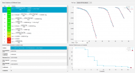
KG1=0.00230261 kp1=-6.471 kp2=31.77 kp3=-5.93e-6 kp4=0.1736 kt1=50 kt2=0.08 kc1=6.721e-4 kc2=7.588e-2 kc3=1.708 ks1=3.462e-6 ks2=3.451e-4 ks3=-1.169e-2 kcs=0.09196 ecref=0 esref=250
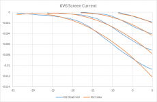
I don't have any screen current data for the tube.
I used these parameters:
KG1=0.00230261 kp1=-6.471 kp2=31.77 kp3=-5.93e-6 kp4=0.1736 kt1=50 kt2=0.08 kc1=6.721e-4 kc2=7.588e-2 kc3=1.708 ks1=3.462e-6 ks2=3.451e-4 ks3=-1.169e-2 kcs=0.09196 ecref=0 esref=250
I don't have any screen current data for the tube.
Hey Gang, does anyone have a 6N7 model they would like to post for me?
I have been using one section of an ECC33 in LTSpice to model the two sections of a 6N7 in parallel, it's the closest thing I have but I would like a real model of a 6N7 before I rip my amp apart.
I want to thank Thomas from Vinylsavor blog for giving me the idea of trying a 6N7 to drive my 6HJ5 amp. I plan to current source the plate @10mA and use a blue LED on the cathode.
Thanks,
-bird
Hey Gang, does anyone have a 6N7 model they would like to post for me?
I found the model below among my models, but cannot guarantee accuracy.
Code:
.SUBCKT TRIODE_6N7 1 2 3 ; Plate Grid Cathode
+ PARAMS: CCG=3.6P  CGP=2.6P CCP=4.6P RGI=2000
+ MU=37 KG1=1680 KP=340 KVB=396 VCT=3.906E-5 EX=1.32
E1 7 0 VALUE={V(1,3)/KP*LOG(1+EXP(KP*(1/MU+(VCT+V(2,3))/SQRT(KVB+V(1,3)*V(1,3)))))}
RE1 7 0 1G  ; TO AVOID FLOATING NODES
G1 1 3 VALUE={(PWR(V(7),EX)+PWRS(V(7),EX))/KG1}
RCP 1 3 1G   ; TO AVOID FLOATING NODES
C1 2 3 {CCG} ; CATHODE-GRID
C2 2 1 {CGP} ; GRID=PLATE
C3 1 3 {CCP} ; CATHODE-PLATE
D3 5 3 DX ; POSITIVE GRID CURRENT
R1 2 5 {RGI} ; POSITIVE GRID CURRENT
.MODEL DX D(IS=1N RS=1 CJO=10PF TT=1N)
.ENDS")
Is it accurate enough? You be the judge...
The above 6N7 SPICE model vs. the GE datasheet:
The above 6N7 SPICE model vs. the GE datasheet:
An externally hosted image should be here but it was not working when we last tested it.
Looks accurate enough to me but I can't seem to get it to work in LTSpice correctly. I mean I don't get any errors but I am getting weird readings like the same voltage at the cathode is appearing on the grid in a simple common cathode gain stage. The model looks different then the ones I am use to so maybe I need to change something in the txt file?
Code:
* ==============================================================
* 6N7_GE Twin triode power amplifier LTSpice model
* Modified Koren model (8 parameters): mean fit error 0.059444mA
* Traced by Wayne Clay on 9/6/2007 using Curve Captor v0.9.1
* from General Electric data sheet
* Note: Positive grid region not modeled
* Inter-electrode capacitances are guesses
* ==============================================================
.subckt 6N7_GE  P G K
    Bp  P K  I=
+ (0.0114397703m)*uramp(V(P,K)*ln(1.0+(-0.5370300777)+exp((7.042163077)+
+ (7.042163077)*((40.286562)+(476.0498871m)*V(G,K))*V(G,K)/sqrt((1.127269255)**2+
+ (V(P,K)-(-24.1176161))**2)))/(7.042163077))**(1.290144231)
    Cgk G K 4p
    Cgp G P 4p
    Cpk P K 3p
.ends 6N7_GEAbove 6N7 model traced over GE datasheet (circles) in Curve Captor.
You are welcome!cogsncogs, thank you that works perfect!!!
Attachments
I've just added a diode model to give some semblance of grid current and to insure covergence. Didn't notice it wasn't there before. 
Code:
* ==============================================================
* 6N7_GE Twin triode power amplifier LTSpice model
* Modified Koren model (8 parameters): mean fit error 0.059444mA
* Traced by Wayne Clay on 9/6/2007 using Curve Captor v0.9.1
* from General Electric data sheet
* Note: Positive grid region not modeled
* Inter-electrode capacitances are guesses
* ==============================================================
.subckt 6N7_GE  P G K
    Bp  P K  I=
+ (0.0114397703m)*uramp(V(P,K)*ln(1.0+(-0.5370300777)+exp((7.042163077)+
+ (7.042163077)*((40.286562)+(476.0498871m)*V(G,K))*V(G,K)/sqrt((1.127269255)**2+
+ (V(P,K)-(-24.1176161))**2)))/(7.042163077))**(1.290144231)
    Cgk G K 4p
    Cgp G P 4p
    Cpk P K 3p
    d3  G K dx1
.model dx1 d(is=1n rs=2k cjo=1pf N=1.5 tt=1n)
.ends 6N7_GEI've just added a diode model to give some semblance of grid current and to insure covergence. Didn't notice it wasn't there before.
Code:* ============================================================== * 6N7_GE Twin triode power amplifier LTSpice model * Modified Koren model (8 parameters): mean fit error 0.059444mA * Traced by Wayne Clay on 9/6/2007 using Curve Captor v0.9.1 * from General Electric data sheet * Note: Positive grid region not modeled * Inter-electrode capacitances are guesses * ============================================================== .subckt 6N7_GE P G K Bp P K I= + (0.0114397703m)*uramp(V(P,K)*ln(1.0+(-0.5370300777)+exp((7.042163077)+ + (7.042163077)*((40.286562)+(476.0498871m)*V(G,K))*V(G,K)/sqrt((1.127269255)**2+ + (V(P,K)-(-24.1176161))**2)))/(7.042163077))**(1.290144231) Cgk G K 4p Cgp G P 4p Cpk P K 3p d3 G K dx1 .model dx1 d(is=1n rs=2k cjo=1pf N=1.5 tt=1n) .ends 6N7_GE
I just updated the model, Thanks again!!

This is related to 47 pentode model.
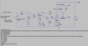
I took your advice and end up with the following model
However, when i tried to simulate, it ran very slowly.. i don't think it works? Where did i go wrong?
See post 1090 -- the LTSpice syntax is a bit different from MSIM -- you need curly brackets.
I used these parameters:
KG1=0.00230261 kp1=-6.471 kp2=31.77 kp3=-5.93e-6 kp4=0.1736 kt1=50 kt2=0.08 kc1=6.721e-4 kc2=7.588e-2 kc3=1.708 ks1=3.462e-6 ks2=3.451e-4 ks3=-1.169e-2 kcs=0.09196 ecref=0 esref=250
I don't have any screen current data for the tube.
I took your advice and end up with the following model
.subckt type47 1 2 3 4
+params: KG1=0.00230261 kp1=-6.471 kp2=31.77 kp3=-5.93e-6 kp4=0.1736 kt1=50 kt2=0.08 kc1=6.721e-4 kc2=7.588e-2 kc3=1.708 ks1=3.462e-6 ks2=3.451e-4 ks3=-1.169e-2 kcs=0.09196 ecref=0 esref=250
E1 7 0 Value={V(1,4)}
E2 8 0 Value={V(3,4)}
E3 9 0 Value={V(2,4)}
RE1 7 0 1e12
G1 1 4 VALUE={(KG1*V(7)+((kp1/(kp2+v(7))+(kp3*v(7))+kp4)-KG1*V(7))/(1+EXP((KT1-V(7))*KT2)))*((kc1*V(8)**2)+kc2*v(8)+kc3)*((ks1*V(9 )**2)+ks2*v(9)+ks3)*(1/(1-kcs*(V(8)-ecref)*(1-V(9)/esref)))}
RCP 1 4 1e12
C1 2 3 2.4e-12
C2 1 2 3.9e-12
C3 1 3 0.7e-12
R1 2 5 2000
D3 5 3 dx
.model dx d(is=1e-9 rs=1 cjo=10e-12)
.ends
However, when i tried to simulate, it ran very slowly.. i don't think it works? Where did i go wrong?
Attachments
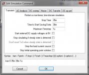
Try changing the Maximum Time Step to 1u in the Transient analysis, it should run pretty fast, although as jackinnj mentioned, this particular model does not contain screen current.However, when i tried to simulate, it ran very slowly.
Try changing the Maximum Time Step to 1u in the Transient analysis, it should run pretty fast, although as jackinnj mentioned, this particular model does not contain screen current.
How fast is "pretty fast"? Been running the simulation for about 10 minutes and i haven't got past 1.5% progress.
Attachments
- Home
- Amplifiers
- Tubes / Valves
- Vacuum Tube SPICE Models