Thanks jazbo8 and jackinnj. The tetrode pins i use is A S G K, in that order.
I took a second look at the model and changed R1 value and D3 pins. It works and at least screen current at idle is close to the the datasheet now.
I took a second look at the model and changed R1 value and D3 pins. It works and at least screen current at idle is close to the the datasheet now.
.subckt type47 1 2 3 4
+params: KG1=0.00230261 kp1=-6.471 kp2=31.77 kp3=-5.93e-6 kp4=0.1736 kt1=50 kt2=0.08 kc1=6.721e-4 kc2=7.588e-2 kc3=1.708 ks1=3.462e-6 ks2=3.451e-4 ks3=-1.169e-2 kcs=0.09196 ecref=0 esref=250
E1 7 0 Value={V(1,4)}
E2 8 0 Value={V(3,4)}
E3 9 0 Value={V(2,4)}
RE1 7 0 1e12
G1 1 4 VALUE={(KG1*V(7)+((kp1/(kp2+v(7))+(kp3*v(7))+kp4)-KG1*V(7))/(1+EXP((KT1-V(7))*KT2)))*((kc1*V(8)**2)+kc2*v(8)+kc3)*((ks1*V(9 )**2)+ks2*v(9)+ks3)*(1/(1-kcs*(V(8)-ecref)*(1-V(9)/esref)))}
RCP 1 4 1e12
C1 2 3 2.4e-12
C2 1 2 3.9e-12
C3 1 3 0.7e-12
R1 2 5 39000
D3 5 4 dx
.model dx d(is=1e-9 rs=1 cjo=10e-12)
.ends
Thanks jazbo8 and jackinnj. The tetrode pins i use is A S G K, in that order.
I took a second look at the model and changed R1 value and D3 pins. It works and at least screen current at idle is close to the the datasheet now.
There is no "G2" in that model, voltage controlled current source between pins 2 and 4.
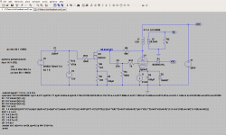
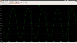
@ballpencil, I've tinkered with your sim in LTspice. I've edited your 47 model as there were a few inconsistencies. I've simplified the diode model from the control grid to the cathode. Also in the sim I've added a reversed biased diode across the current source to aid in convergence. Below I've attached the edited model, a LTspice file and two screen shots. Be aware that I'm not firing on all cylinders today, so I might have made a goof or two. 
Code:
.subckt type47 1 2 3 4 ; A S G K
+params: KG1=0.00230261 kp1=-6.471 kp2=31.77 kp3=-5.93e-6 kp4=0.1736 kt1=50 kt2=0.08 kc1=6.721e-4 kc2=7.588e-2 kc3=1.708 ks1=3.462e-6 ks2=3.451e-4 ks3=-1.169e-2 kcs=0.09196 ecref=0 esref=250
E1  7 0 Value={V(1,4)}
E2  8 0 Value={V(3,4)}
E3  9 0 Value={V(2,4)}
RE1 7 0 1e12
G1  1 4 VALUE={(KG1*V(7)+((kp1/(kp2+v(7))+(kp3*v(7))+kp4)-KG1*V(7))/(1+EXP((KT1-V(7))*KT2)))*((kc1*V(8)**2)+kc2*v(8)+kc3)*((ks1*V(9 )**2)+ks2*v(9)+ks3)*(1/(1-kcs*(V(8)-ecref)*(1-V(9)/esref)))}
RCP 1 4 1e12
C1  3 4 2.4e-12
C2  1 4 3.9e-12
C3  1 3 0.7e-12
d3  3 4 dx1
.model dx1 d(is=1n rs=2k cjo=0.1p N=1.5 tt=1n)
.ends
Attachments
LTSpice and tubes
Hi
I'm newbie in this forum and TLspice. I like design a tube preamp with a 6n16 tube. I found this file .sub:
triodes.sub line 90.
https://gist.github.com/chanmix51/6947361
where i find this tube but i don't know how to use this information. How can i make a 6n16 symbol and simulate it?
thanks for your help
Hello all!
I'm newbie and maybe that question was already asked, but is there model of vacuum diode? Not triode/pentode, but simple vacuum diode?
I tried make it by myself, using Stefano Perugini's diode definition, but failed (had "The instance has more connections than the definition" error when redrawing triode to diode and trying to use in in the circuit):
Thanks for your help!*
* Diode definition by Stefano Perugini
*
.SUBCKT Diode P C
E1 1 0 VALUE = {KA + KB * V(P,C)}
E2 2 0 VALUE = {V(P,C) + EPS}
G1 P C VALUE = {V(1) * (PWR(V(2), EX) + PWRS(V(2), EX))/2}
C1 P C {CCP}
.ENDS
Ah, I understood!
But I also used model with all parameters and .inc file with definition and it gave me same error.
But I also used model with all parameters and .inc file with definition and it gave me same error.
* 6AL5 code from General Electric 1954 generated by kurvmatch
*
.SUBCKT 6AL5 1 2
XZ1 1 2 Diode CCP=2.5P KA=0.002339 EX=1.42 KB=-0.000008 EPS=0.100000
.ENDS
I am in need of accurate LTspice models for the following Nuvistors:
7895 Triode and 7587 Tetrode. Both are used in the Ampex MR-70 electronics that I am restoring/hot-rodding.
Although I am a serious user of LTspice, I do not have the math chops and model understanding to make my own models without some initial hand-holding. I am aware that there are Koren style models that supposedly work OK with triodes but are not accurate for tetrodes. I understand that there are some other model families that are supposedly better, but I am way down on the learning curve to even be able to determine what model is working correctly or not.
Data sheets for these Nuvistors are available complete with curves and numeric data. I just don't know personally how to translate the data into a model so I can try out the circuit topologies that I want to examine.
Thank you in advance for any help you can give me.
Steve Hogan
714 871-6636
714 904-6636 (cell)
Last edited by a moderator:
I just don't know personally how to translate the data into a model so I can try out the circuit topologies that I want to examine.
Maybe I should do a youtube video...it's not difficult.
7859 SPICE Model
Code:
*
* Generic triode model: 7895_AN
* Copyright 2003--2008 by Ayumi Nakabayashi, All rights reserved.
* Version 3.10, Generated on Sun Apr 17 16:20:27 2016
*               Anode
*               | Grid
*               | | Cathode
*               | | |
.SUBCKT 7895_AN A G K
BGG   GG   0 V=V(G,K)+0.3310575
BM1   M1   0 V=(0.021476228*(URAMP(V(A,K))+1e-10))**-2.5656488
BM2   M2   0 V=(0.3689448*(URAMP(V(GG)+URAMP(V(A,K))/29.383894)+1e-10))**4.0656488
BP    P    0 V=0.0099212093*(URAMP(V(GG)+URAMP(V(A,K))/79.643063)+1e-10)**1.5
BIK   IK   0 V=U(V(GG))*V(P)+(1-U(V(GG)))*0.039321732*V(M1)*V(M2)
BIG   IG   0 V=0.0049606047*URAMP(V(G,K))**1.5*(URAMP(V(G,K))/(URAMP(V(A,K))+URAMP(V(G,K)))*1.2+0.4)
BIAK  A    K I=URAMP(V(IK,IG)-URAMP(V(IK,IG)-(0.0051480463*URAMP(V(A,K))**1.5)))+1e-10*V(A,K)
BIGK  G    K I=V(IG)
* CAPS
CGA   G    A 0.9p
CGK   G    K 4.2p
CAK   A    K 1.7p
.ENDS7587 Tetrode Model
Code:
*
* Generic pentode model: 7587_AN
* Copyright 2003--2008 by Ayumi Nakabayashi, All rights reserved.
* Version 3.10, Generated on Sun Apr 17 19:35:04 2016
*               Anode
*               | Screen Grid
*               | |  Control Grid
*               | |  |  Cathode
*               | |  |  |
.SUBCKT 7587_AN A G2 G1 K
BGG   GG   0 V=V(G1,K)+-0.93083831
BM1   M1   0 V=(0.056230366*(URAMP(V(G2,K))+1e-10))**-1.8620379
BM2   M2   0 V=(0.44615798*(URAMP(V(GG)+URAMP(V(G2,K))/9.8495184)))**3.3620379
BP    P    0 V=0.017475627*(URAMP(V(GG)+URAMP(V(G2,K))/22.076302))**1.5
BIK   IK   0 V=U(V(GG))*V(P)+(1-U(V(GG)))*0.026138039*V(M1)*V(M2)
BIG   IG   0 V=0.0087378137*URAMP(V(G1,K))**1.5*(URAMP(V(G1,K))/(URAMP(V(A,K))+URAMP(V(G1,K)))*1.2+0.4)
BIK2  IK2  0 V=V(IK,IG)*(1-0.4*(EXP(-URAMP(V(A,K))/URAMP(V(G2,K))*15)-EXP(-15)))
BIG2T IG2T 0 V=V(IK2)*(0.71533934*(1-URAMP(V(A,K))/(URAMP(V(A,K))+10))**1.5+0.28466066)
BIK3  IK3  0 V=V(IK2)*(URAMP(V(A,K))+2650)/(URAMP(V(G2,K))+2650)
BIK4  IK4  0 V=V(IK3)-URAMP(V(IK3)-(0.0099385622*(URAMP(V(A,K))+URAMP(URAMP(V(G2,K))-URAMP(V(A,K))))**1.5))
BIP   IP   0 V=URAMP(V(IK4,IG2T)-URAMP(V(IK4,IG2T)-(0.0099385622*URAMP(V(A,K))**1.5)))
BIAK  A    K I=V(IP)+1e-10*V(A,K)
BIG2  G2   K I=URAMP(V(IK4,IP))
BIGK  G1   K I=V(IG)
* CAPS
CGA   G1  A  0.015p
CGK   G1  K  4.2p
C12   G1  G2 2.8p
CAK   A   K  1.4p
.ENDSMaybe I should do a youtube video...it's not difficult.
Yes Please !
Thank you .
1P24B Pentode Model
Code:
*
* Generic pentode model: 1P24B_AN
* Copyright 2003--2008 by Ayumi Nakabayashi, All rights reserved.
* Version 3.10, Generated on Mon Apr 18 09:52:29 2016
*                Anode
*                | Screen Grid
*                | |  Control Grid
*                | |  |  Cathode
*                | |  |  |
.SUBCKT 1P24B_AN A G2 G1 K
BGG   GG   0 V=V(G1,K)+0.78441583
BM1   M1   0 V=(0.050203142*(URAMP(V(G2,K))+1e-10))**-0.42612758
BM2   M2   0 V=(0.77876462*(URAMP(V(GG)+URAMP(V(G2,K))/4.4068036)))**1.9261276
BP    P    0 V=0.00078336376*(URAMP(V(GG)+URAMP(V(G2,K))/5.6587106))**1.5
BIK   IK   0 V=U(V(GG))*V(P)+(1-U(V(GG)))*0.0004582081*V(M1)*V(M2)
BIG   IG   0 V=0.00039168188*URAMP(V(G1,K))**1.5*(URAMP(V(G1,K))/(URAMP(V(A,K))+URAMP(V(G1,K)))*1.2+0.4)
BIK2  IK2  0 V=V(IK,IG)*(1-0.4*(EXP(-URAMP(V(A,K))/URAMP(V(G2,K))*15)-EXP(-15)))
BIG2T IG2T 0 V=V(IK2)*(0.94497705*(1-URAMP(V(A,K))/(URAMP(V(A,K))+10))**1.5+0.05502295)
BIK3  IK3  0 V=V(IK2)*(URAMP(V(A,K))+10000)/(URAMP(V(G2,K))+10000)
BIK4  IK4  0 V=V(IK3)-URAMP(V(IK3)-(0.00060825471*(URAMP(V(A,K))+URAMP(URAMP(V(G2,K))-URAMP(V(A,K))))**1.5))
BIP   IP   0 V=URAMP(V(IK4,IG2T)-URAMP(V(IK4,IG2T)-(0.00060825471*URAMP(V(A,K))**1.5)))
BIAK  A    K I=V(IP)+1e-10*V(A,K)
BIG2  G2   K I=URAMP(V(IK4,IP))
BIGK  G1   K I=V(IG)
* CAPS
CGA   G1  A  0.008p
CGK   G1  K  4.5p
C12   G1  G2 3p
CAK   A   K  4p
.ENDS- Home
- Amplifiers
- Tubes / Valves
- Vacuum Tube SPICE Models