13E1 SPICE Models
Here are the SPICE models for the 13E1 based on the sample that you provided, please note that your sample does not seem to match that of the AEI datasheet. The sample's current seems to be a bit lower than the datasheet but as long as the output pairs are well matched, you should have no problem, you could also run the screen voltage a bit higher to compensate for the difference.
13E1 Pentode Model:
13E1 Triode-Connected Model:
Here are the SPICE models for the 13E1 based on the sample that you provided, please note that your sample does not seem to match that of the AEI datasheet. The sample's current seems to be a bit lower than the datasheet but as long as the output pairs are well matched, you should have no problem, you could also run the screen voltage a bit higher to compensate for the difference.
13E1 Pentode Model:
Code:
*
* Generic pentode model: 13E1_AN
* Copyright 2003--2008 by Ayumi Nakabayashi, All rights reserved.
* Version 3.10, Generated on Fri Feb 06 15:25:21 2015
*               Plate
*               | Screen Grid
*               | |  Control Grid
*               | |  |  Cathode
*               | |  |  |
.SUBCKT 13E1_AN A G2 G1 K
BGG   GG   0 V=V(G1,K)+0.81627168
BM1   M1   0 V=(0.10658069*(URAMP(V(G2,K))+1e-10))**-0.91538648
BM2   M2   0 V=(0.62101863*(URAMP(V(GG)+URAMP(V(G2,K))/3.5558165)))**2.4153865
BP    P    0 V=0.0072073829*(URAMP(V(GG)+URAMP(V(G2,K))/5.7257807))**1.5
BIK   IK   0 V=U(V(GG))*V(P)+(1-U(V(GG)))*0.0045860555*V(M1)*V(M2)
BIG   IG   0 V=0.0036036914*URAMP(V(G1,K))**1.5*(URAMP(V(G1,K))/(URAMP(V(A,K))+URAMP(V(G1,K)))*1.2+0.4)
BIK2  IK2  0 V=V(IK,IG)*(1-0.4*(EXP(-URAMP(V(A,K))/URAMP(V(G2,K))*15)-EXP(-15)))
BIG2T IG2T 0 V=V(IK2)*(0.940677708*(1-URAMP(V(A,K))/(URAMP(V(A,K))+10))**1.5+0.059322292)
BIK3  IK3  0 V=V(IK2)*(URAMP(V(A,K))+1964)/(URAMP(V(G2,K))+1964)
BIK4  IK4  0 V=V(IK3)-URAMP(V(IK3)-(0.0055720165*(URAMP(V(A,K))+URAMP(URAMP(V(G2,K))-URAMP(V(A,K))))**1.5))
BIP   IP   0 V=URAMP(V(IK4,IG2T)-URAMP(V(IK4,IG2T)-(0.0055720165*URAMP(V(A,K))**1.5)))
BIAK  A    K I=V(IP)+1e-10*V(A,K)
BIG2  G2   K I=URAMP(V(IK4,IP))
BIGK  G1   K I=V(IG)
* CAPS
CGA   G1  A  1.3p
CGK   G1  K  33.6p
C12   G1  G2 22.4p
CAK   A   K  20p
.ENDS
13E1 Triode-Connected Model:
Code:
*
* Generic triode model: 13E1_T_AN
* Copyright 2003--2008 by Ayumi Nakabayashi, All rights reserved.
* Version 3.10, Generated on Fri Feb 06 15:11:49 2015
*                 Plate
*                 | Grid
*                 | | Cathode
*                 | | |
.SUBCKT 13E1_T_AN A G K
BGG   GG   0 V=V(G,K)+0.81627168
BM1   M1   0 V=(0.10658069*(URAMP(V(A,K))+1e-10))**-0.91538648
BM2   M2   0 V=(0.62101863*(URAMP(V(GG)+URAMP(V(A,K))/3.5558165)+1e-10))**2.4153865
BP    P    0 V=0.0072073829*(URAMP(V(GG)+URAMP(V(A,K))/5.7257807)+1e-10)**1.5
BIK   IK   0 V=U(V(GG))*V(P)+(1-U(V(GG)))*0.0045860555*V(M1)*V(M2)
BIG   IG   0 V=0.0036036914*URAMP(V(G,K))**1.5*(URAMP(V(G,K))/(URAMP(V(A,K))+URAMP(V(G,K)))*1.2+0.4)
BIAK  A    K I=URAMP(V(IK,IG)-URAMP(V(IK,IG)-(0.0055720165*URAMP(V(A,K))**1.5)))+1e-10*V(A,K)
BIGK  G    K I=V(IG)
* CAPS
CGA   G    A 1.3p
CGK   G    K 56p
CAK   A    K 20p
.ENDS
Last edited:
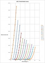
13E1 in tetrode mode
Jazbo
Many thanks. I too had looked at the AEI data sheet, and the current is considerably below that. But I've found triode models elsewhere for the 13E1 and the data from mine is similar.
Currently all the tubes I have are from the same batch. I however have another batch and I will try these out soon and tell you what happens.
Many thanks again.
They look fine, since the syntax are correct, no idea why they would fail to converge in Multisim...
Apparently Multisim has a problem with multiple behavioral directives.
Interesting that Analog Devices has recently migrated to SIMPLIS (ADIsimPE powered by SIMetrix/SIMPLIS | Analog Devices) from Multisim (Expiration Notice of Multisim Component Evaluator Analog Devices Edition - National Instruments).
Interesting that Analog Devices has recently migrated to SIMPLIS (ADIsimPE powered by SIMetrix/SIMPLIS | Analog Devices) from Multisim (Expiration Notice of Multisim Component Evaluator Analog Devices Edition - National Instruments).
Is this the same application that Mouser is offering as MultiSIM BLUE?
MultiSIM BLUE | Mouser
From MultiSIM BLUE > About > FAQs Q9
"MultiSIM BLUE is the FREE version of NI's Multisim. It incorporates the 50 part limit of Multisim Student, the simulation engine of Multisim Base and the full version of Ultiboard Power Pro. In addition, you get a 100,000+ part database and tight integration with the Mouser website."
From NI Multisim Professional Simulation Driven Instruments and Analyses - National Instruments it's quite limited in analyses and instruments compared to both the Full and Power Pro versions. However, compared to the Power Pro version, the Student version has all of the instruments and only lacks Batched, Distortion, Noise, Pole Zero, Sensitivity, Trace Width, Transfer Function, and User Defined Analyses. I know that the Distortion analysis is broken but haven't tried any of those others.
Smart business move by Mouser though!
If you're interested in trying Multisim, I'd suggest the free trial download. Unlike the other versions, it includes a decent range of easy to use transformers and some of the most common vacuum tubes.
If you're interested in trying Multisim, I'd suggest the free trial download. Unlike the other versions, it includes a decent range of easy to use transformers and some of the most common vacuum tubes.
I have downloaded it but haven't gotten around to trying it yet. The 50 part limit scares me a little, although that might be enough for most projects. But I do have some designs that exceed that limit so I'm not sure it makes sense to use two different sets of design tools depending on the number of parts a circuit might have.
Does anyone have any experience with MultiSIM BLUE and, if so, is it worth making the switch from LTspice and a capable PCB design application?
I think you will be better off with something else... here is a short review.Does anyone have any experience with MultiSIM BLUE and, if so, is it worth making the switch from LTspice and a capable PCB design application?
I think you will be better off with something else... here is a short review.
This was extremely helpful -- thanks. Although the MultiSIM BLUE concept seemed like a good idea at the time, there are too many limitations and unknowns to make it worth the time and energy for me to learn a new tool. I guess I'll be sticking with what I already know.
Ray,
It’s too bad MultiSIM BLUE is so restrictive, otherwise it might be worth trying. After downloading and trying Analog Device’s recent replacement for MULTISIM, ADIsimPE (ADIsimPE powered by SIMetrix/SIMPLIS | Analog Devices), I downloaded and tried the recently updated/latest version of LTspice (Linear Technology - Design Simulation and Device Models). Both were surprising easy to learn and use – especially with Duncan Monroe’s guidance on LTspice (LTSpice and vacuum tube models)! After changing the 0.01F output coupling capacitor to a more reasonable 10nF in my 12AX7 test circuit (attached), both LTSpice and MULTISIM provided identical output levels, but ADIsimPE’s with only about half what it should have been. And, unlike MULTISIM, LTspice worked with the Ayumi model (after changing ^ to **).
Given my very limited experience with LTspice, here are my thoughts on how it compares to MULTISIM. To me LTspice’s simulations are analogous to Audacity’s (Audacity: Free Audio Editor and Recorder) pre-recorded signal analyses whereas MULTISIM’s simulations are analogous to TrueRTA’s (TrueRTA Audio Spectrum Analyzer Software) real-time signal analyses. I.e. unlike LTspice, MULTSIM allows the placement of numerous probes and instruments to enable the measurement of multiple circuit performance parameters while the simulation runs. The effect of modifying input and component values while the simulation runs are “instantly” reflected in those measurements.
MULTISIM also provides LTspice type analyses, but seems to have some problems doing so. Both its AC and Distortion analyses appear to be broken.
Also, MULTISIM’s user interface, although sometimes counterintuitive, seems much more sophisticated than LTspice’s.
Attachments
Given my very limited experience with LTspice, here are my thoughts on how it compares to MULTISIM. To me LTspice’s simulations are analogous to Audacity’s (Audacity: Free Audio Editor and Recorder) pre-recorded signal analyses whereas MULTISIM’s simulations are analogous to TrueRTA’s (TrueRTA Audio Spectrum Analyzer Software) real-time signal analyses. I.e. unlike LTspice, MULTSIM allows the placement of numerous probes and instruments to enable the measurement of multiple circuit performance parameters while the simulation runs. The effect of modifying input and component values while the simulation runs are “instantly” reflected in those measurements.
MULTISIM also provides LTspice type analyses, but seems to have some problems doing so. Both its AC and Distortion analyses appear to be broken.
Also, MULTISIM’s user interface, although sometimes counterintuitive, seems much more sophisticated than LTspice’s.
Thanks again for the comparison. While I sometimes wish for a few more features in LTspice, I'll probably stick with it because (1) it is free, and (2) it has no built-in restrictions on number of components, etc. But I do wish it had better integration with PCB design tools. Although LTspice can export a netlist, I haven't been terribly successful using that feature yet. Maybe I just need to devote more time to playing with it.
812A SPICE Model
You can try this one, not sure how close the Shuguang is to the real RCA though...
anybody have a model of the 812A ? I see these are available also as new from Shuguang, so it might be interesting to try some circuits with these..
You can try this one, not sure how close the Shuguang is to the real RCA though...
Code:
*
* Generic triode model: 812A_AN
* Copyright 2003--2008 by Ayumi Nakabayashi, All rights reserved.
* Version 3.10, Generated on Mon Feb 09 08:53:40 2015
*               Plate
*               | Grid
*               | | Cathode
*               | | |
.SUBCKT 812A_AN A G K
BGG   GG   0 V=V(G,K)+-0.96244725
BM1   M1   0 V=(0.0048617253*(URAMP(V(A,K))+1e-10))**-0.23069326
BM2   M2   0 V=(0.86670471*(URAMP(V(GG)+URAMP(V(A,K))/27.417281)+1e-10))**1.7306933
BP    P    0 V=0.00083219338*(URAMP(V(GG)+URAMP(V(A,K))/31.633936)+1e-10)**1.5
BIK   IK   0 V=U(V(GG))*V(P)+(1-U(V(GG)))*0.0005403282*V(M1)*V(M2)
BIG   IG   0 V=0.00041609669*URAMP(V(G,K))**1.5*(URAMP(V(G,K))/(URAMP(V(A,K))+URAMP(V(G,K)))*1.2+0.4)
BIAK  A    K I=URAMP(V(IK,IG)-URAMP(V(IK,IG)-(0.00045586739*URAMP(V(A,K))**1.5)))+1e-10*V(A,K)
BIGK  G    K I=V(IG)
* CAPS
CGA   G    A 5.5p
CGK   G    K 5.4p
CAK   A    K 0.8p
.ENDS- Home
- Amplifiers
- Tubes / Valves
- Vacuum Tube SPICE Models