Yes, good quality chokes are not easily available. The good ones are expensive. You may want to custom order in China or contact Kevin of Valab in Taiwan selling 50H chokes on eBay at 50H 100mA Anode Plate Choke for 300B 2A3 71A EL34 KT88 One Pair | eBay.. . . I'm no inductance L1, . . .


The problem may be:Not satisfied with the sound.
1. 4 ma bias on VFET absolutely too low, can not drive MJE15031, sound thin and harsh, no dynamics. Try to increase to 15-30 ma or change MJE15031 to 2SJ162 or TIP147
2. 10 ma output bias a little low, crossover distortion - harsh and subdued detail. Try 30-50 ma.
Last edited:
Thank you for your help.
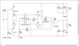
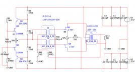
Has now changed to #44 circuits, Q3=Q4=7.5mA.
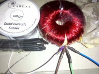
Sounds good, but because of reasons to use output transformers power transformers, high frequencies and some darker. Actual measurements from the 15kHz began to fall. Next time you use the toroidal transformer output. 120V+120V:12V+12V 30W。
Has now changed to #44 circuits, Q3=Q4=7.5mA.
Sounds good, but because of reasons to use output transformers power transformers, high frequencies and some darker. Actual measurements from the 15kHz began to fall. Next time you use the toroidal transformer output. 120V+120V:12V+12V 30W。
Attachments
![HUR}_XD]HY_BO(7ZP@K_LWN.jpg](/community/data/attachments/389/389696-b1385aa9c7c502d18e8c6d7eb554fdac.jpg)
7.5 ma and 30V = 225mW, good for headphone. If the sound is really good, you could try small line-out/headphone output transformer similar to Edcor xpp1-10kct-600 for high impedance headphone or xpp10-16-8k for low impedance headphone.
7.5 ma and 30V = 225mW, good for headphone. If the sound is really good, you could try small line-out/headphone output transformer similar to Edcor xpp1-10kct-600 for high impedance headphone or xpp10-16-8k for low impedance headphone.
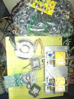
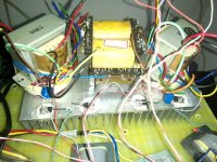
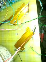
This is my bookshelf for my FE126EN wide-band Horn custom-made amplifier, you calculate is a class a power, I did the AB class amplifier, expected output is 2~3W.
Understood Kiven, just pointing out if the sound is really good, you may offer headphone amp kit as group buy when more parts become available. I believe many would be interested.This is my bookshelf for my FE126EN wide-band Horn custom-made amplifier, you calculate is a class a power, I did the AB class amplifier, expected output is 2~3W.
Understood Kiven, just pointing out if the sound is really good, you may offer headphone amp kit as group buy when more parts become available. I believe many would be interested.
That's impossible, because I have only 6 VFET from LAO CAO free samples. I can't get more VFET.
If LAO CAO July sale VFET on EBAY, I believe there are more people interested in it.
how does this sound?
Yuo have chosen to use a tube type topology in your design. It would be interesting to compare it to a tube amp. I would get rid if the first transformer and drive the output Jfets with a 2N5551 concertina.
I feel sound different transistor amplifiers, tube amplifiers are not the same, feeling more active than transistor amplifier, this game is not easy to describe, you have to hear it for yourself to feel it. Because everyone likes to sound different, the sound is good or bad is a borderline, but I liked the sound.
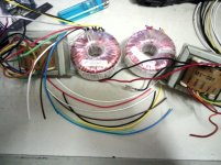
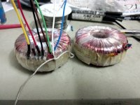
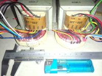
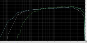
For testing 3 types of "output" Transformers,
A: the square power transformer, 115V+115V:12V+12V, sub in parallel, equivalent impedance 2,939:8 Ohms.
B:EI line transformer, 0,170,330,500,1K,2K:8 ohms, 0,500,2K:8 Ohms.
C: toroidal power transformer, 120V+120V:12V+12V, sub in parallel, equivalent impedance 3,200:8 Ohms.
Test load was 50 Watt 8 Ohm resistor.
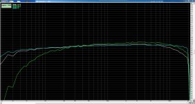
Frequency response test results in 3 colors, respectively.
Interested people to guess the color is kind of transformer. The answers in a few days.
A: the square power transformer, 115V+115V:12V+12V, sub in parallel, equivalent impedance 2,939:8 Ohms.
B:EI line transformer, 0,170,330,500,1K,2K:8 ohms, 0,500,2K:8 Ohms.
C: toroidal power transformer, 120V+120V:12V+12V, sub in parallel, equivalent impedance 3,200:8 Ohms.
Test load was 50 Watt 8 Ohm resistor.
Frequency response test results in 3 colors, respectively.
Interested people to guess the color is kind of transformer. The answers in a few days.
Attachments
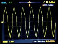
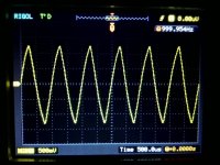
Actual measurement waveform distortion, in order to be able clear distortion, using a triangle wave, maximum distortion voltage of 1V.
Finally check out the problem is that the source resistor bias.
Finally check out the problem is that the source resistor bias.
Attachments

- Status
- This old topic is closed. If you want to reopen this topic, contact a moderator using the "Report Post" button.
- Home
- Amplifiers
- Pass Labs
- V-FET (SIT) amplifier production