Hi Kiven,
You may want to change the input p channel jfet label to 2SJ74 or LSK74. A J174 is an n channel jfet manufactured by Fairchild and some others.
Thank you, I am careless freshman was a typo. J74
Actually being used is K364,J104.
Hi Kiven,
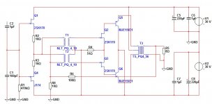
May I suggest the following circuit to test. Stable and simple.
Still need to adapt L1 and P2 value for your particular Vfet bias point.
I need an AB class amplifier, class a amplifier is not taken into account.
Similar to yours at #25, the circuit is a building block that will work well at class AB when operated push-pull as in #21. I was mainly proposing a lateral mosfet for output and the use of an inductor as the vfet load. You may find it useful that distortion is low and the sonic pleasing for a very simple circuit. But no problem, please do what you think is best.

I can't see the picture.Similar to yours at #25, the circuit is a building block that will work well at class AB when operated push-pull as in #21. I was mainly proposing a lateral mosfet for output and the use of an inductor as the vfet load. You may find it useful that distortion is low and the sonic pleasing for a very simple circuit. But no problem, please do what you think is best.
Sorry Kiven, attached on the following post #31 is an example of push-pull class AB configuration.I can't see the picture.
The circuit presented is a very basic starting point that still requires optimization I currently am unable to help you with measurements nor listening test due to parts unavailability and lack of your design goals.
For your consideration, design points are :
- fast warmup
- thermally stable, no need for thermal compensation whatsoever
- simple non global feedback 2 stage amplification with only 1 voltage amplification stage - more stable against oscillation problem
- no base current induced distortion - unlike bipolar
- less distortion compared to a transformer based phase splitting design
- easy modification to Class A or Class B operation when needed
- maximized Vfet sonic signature with direct coupling and the J162 source follower configuration
- the J162 has a more triodish transfer function compared to the complementary K1058 with unique sonic signature
- sonically smoother and less harsh due to L1 inductor loading compared to CCS or resistance loading
- OT1 protects speakers against component failure
Drawbacks are:
- needs to adjust operating point for every circuit or active components matching - not practical for mass production
- typical to simple non global feedback system, parts selection will have greater impact on sonic signature
- lower damping factor due to comparably higher output impedance compared to bipolar or vertical mosfet
- heavy in weight due to large L1 and OT1
- can be extremely expensive if your customer (never forget your first customer, your own ears
 ) demands exotic use of audiophile material such as nickel permalloy core, nanocrystaline amorphous core, silver wire winding or branded boutique capacitor, resistor and other parts.
Important things and changes that may interest you are:
- May require 220 - 1k ohm gate stopper resistor at Vfet if there is an indication of oscillation (test with 10-20kHz square wave input, check for ringing)
- Needs to make sure that there is no DC present at source - absolutely needs input transformer or input coupling capacitor for commercial production
- 50H+50H L1 with <25+25 ohm dcr and 200+200mH primary 4:1 OT1 with <4+4 ohm primary dcr with <1ohm secondary dcr and exotic material may be chosen higher performance.
- 10H+10H for L1 with <25+25 ohm dcr and 100+100mH primary 2:1 OT1 with <8+8 ohm primary dcr may be used for a mid-high duty amp on a biamp setup to reduce weight or cost
- In asia, there is an already sizable and growing high end market that prefers transformer induced sonic signature currently lacking of selection for reliable and low maintenance solid state amp, but perhaps still not large enough to justify mass production
Hope this can help you make better decision in choosing options available to you. Maybe other members would kindly share experience, add comments or correct any unintentional mistake I may have made.

Last edited:
Hi sdman,Is there an source for OT1 and specs?
I am only aware of Susan Parker's Zeus OT by Sowter 9840 at £190.98. However if you are in the USA, Jack Elliano at Electra-Print.com High-Fidelity Audio Tranformers and Tube Amplifiers should be able to make one for you, he custom made the OT for Mr. Pass Arch Nemesis amp. You can give 50W PP 256 : 8 ohm impedance ratio or 4 : 1 winding ratio and 300mA DC current bias for spec.
Mine were custom wound with a split bobbin of 400 turn of 0.45mm wire for primary and 200 turn of 0.6mm wire for secondary winding on a 38mm tongue with a stack height of 35 mm. Layered 200P, 200S and 200P. Winding opposing directions for the 2 sections to reduce interwinding capacitance and hum pickup. All primary windings are connected in series and all secondary windings are paralleled to give 4:1 winding ratio.
It sounds better to connect the innermost ends of the primary together and use it as the center tap. Just connect one inner to one outer winding wire of the secondaries noting winding polarity.
I'm designing for an economy version so I use el cheapo GOSS power transformer core with 5 : 5 interleave stacking to prevent saturation due to DC current imbalance and improve linearity. Sounds acceptable with HF a bit rolled off. Just ordered a new OT using bifilar winding method as an attempt to improve performance. Should be ready in a couple of weeks.
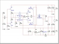
Sorry Kiven, attached on the following post #31 is an example of push-pull class AB configuration.
The circuit presented is a very basic starting point that still requires optimization I currently am unable to help you with measurements nor listening test due to parts unavailability and lack of your design goals.
For your consideration, design points are :
- fast warmup
- thermally stable, no need for thermal compensation whatsoever
- simple non global feedback 2 stage amplification with only 1 voltage amplification stage - more stable against oscillation problem
- no base current induced distortion - unlike bipolar
- less distortion compared to a transformer based phase splitting design
- easy modification to Class A or Class B operation when needed
- maximized Vfet sonic signature with direct coupling and the J162 source follower configuration
- the J162 has a more triodish transfer function compared to the complementary K1058 with unique sonic signature
- sonically smoother and less harsh due to L1 inductor loading compared to CCS or resistance loading
- OT1 protects speakers against component failure
Drawbacks are:
- needs to adjust operating point for every circuit or active components matching - not practical for mass production
- typical to simple non global feedback system, parts selection will have greater impact on sonic signature
- lower damping factor due to comparably higher output impedance compared to bipolar or vertical mosfet
- heavy in weight due to large L1 and OT1
- can be extremely expensive if your customer (never forget your first customer, your own ears
Important things and changes that may interest you are:
- May require 220 - 1k ohm gate stopper resistor at Vfet if there is an indication of oscillation (test with 10-20kHz square wave input, check for ringing)
- Needs to make sure that there is no DC present at source - absolutely needs input transformer or input coupling capacitor for commercial production
- 50H+50H L1 with <25+25 ohm dcr and 200+200mH primary 4:1 OT1 with <4+4 ohm primary dcr with <1ohm secondary dcr and exotic material may be chosen higher performance.
- 10H+10H for L1 with <25+25 ohm dcr and 100+100mH primary 2:1 OT1 with <8+8 ohm primary dcr may be used for a mid-high duty amp on a biamp setup to reduce weight or cost
- In asia, there is an already sizable and growing high end market that prefers transformer induced sonic signature currently lacking of selection for reliable and low maintenance solid state amp, but perhaps still not large enough to justify mass production
Hope this can help you make better decision in choosing options available to you. Maybe other members would kindly share experience, add comments or correct any unintentional mistake I may have made.
Thank you for your advice.
But before I saw your suggestion already on Taobao bought a second-hand "JENSEN JE-123A".
So, DIY#22 listen to sound good or bad.
Attachments
transformers
quite like the push pull idea. I have a similar design using a tube and a jfet/depletion mosfet cascode.
This are the transformers I use with great results.
http://shop.plitron.com/specs/415200.pdf
http://shop.plitron.com/specs/414400.pdf
quite like the push pull idea. I have a similar design using a tube and a jfet/depletion mosfet cascode.
This are the transformers I use with great results.
http://shop.plitron.com/specs/415200.pdf
http://shop.plitron.com/specs/414400.pdf
quite like the push pull idea. I have a similar design using a tube and a jfet/depletion mosfet cascode.
This are the transformers I use with great results.
http://shop.plitron.com/specs/415200.pdf
http://shop.plitron.com/specs/414400.pdf
Thank you for the information.
Hi Kiven,
May I suggest the following circuit to test. Stable and simple.
Still need to adapt L1 and P2 value for your particular Vfet bias point.
Thanks
This is a very good idea!!!
Last edited:
Member
Joined 2009
Paid Member
Very good.
You can easily modify #22 by adding a suitable L1 , P2, P3 and change the MJE15031 to 2SJ162 easily enough later. Good luck.
Your L1 is very clever in the circuit, it is really very creative idea.
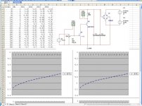
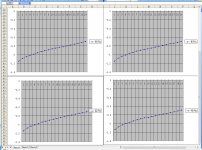
But I'm no inductance L1, 15031, I've bought and test charts that you see in front of me, 2 pair of composite transistors is very good.
So, I'll do 22# circuit diagram, the next time I find L1, will try to be your idea.
BTW, my English is very poor, it makes it difficult to read, I'm sorry.
- Status
- This old topic is closed. If you want to reopen this topic, contact a moderator using the "Report Post" button.
- Home
- Amplifiers
- Pass Labs
- V-FET (SIT) amplifier production