Thanks for the fast replies and clear photos.
It appears that your circuit board layout is the same as mine.
One thing I want to ask: what was your decision to use a 2uF cap? Is there any math behind the decision? Even though my school days background was in electrical engineering, I do not know enough behind audio design to comprehen why the substitution is only 2uF compared to 1000uF lytic that was on there before. I guess 3 caps were used in parallel in the existing circuit design to decouple the DC offset (3 caps per audio channel)?
One final request, can you show another photo for the solder points for the auricaps?
Mucho thanks!
Kuro
Hi Kuro. Physical size, anything larger won't likely fit in the chassis. It brings up a good point, you should measure the impedance to ground either side of the cap to be replaced (unit off of course) to confirm this latest version will still work with a ~2uF cap.
Benchmark probably double-bypassed to keep the lowest possible drive impedance into the following stage to high frequencies though it's hard to say.
Benchmark probably double-bypassed to keep the lowest possible drive impedance into the following stage to high frequencies though it's hard to say.
Thanx rdf.
Kuro, just solder them on the respective pads that original C13 & C14 will leave exposed when taken out.
The 1000uF was not chosen because it takes so much, but because the lower the frequency corner, the less distortion a lytic cap provides. Also the bypasses are an engineering effort to squeeze quality without the $ again. Its a rather budget unit, but well thought out.
Around 4uF is best*, but 2uF was enough and the lid could still fit. If you don't mind aesthetics, chuck 4uF caps right on the chips and smd to the left, with hot glue. They will have enough roof clearance that way.
*4uF -3dB 5Hz, 2uF -3dB 10Hz. For best sub LF phase = nothing fits than quality electrolytics at 22uF and up. You can experiment with those and an Auricap bypass. I prefer the pure Auricap sound and I don't care for super low phase etc because I already have Audionote OPTs in my power amps to screw there better, as almost any output iron will do under 20Hz.
Hi Salas,
I managed to find a local shop that has 2.2uF 200V Auri's. I'm going to see if I can get them later today.
When you said I need to measure impedance, you mean on the input and output side of the caps in relative to ground? What should be the expected values?
Should it resistance that I'm measuring? When you said impedance, I immediately would think AC waveform, in which I do not have the equipment to do that measurement.
Kuro
Hi Salas,
Do you think 4uF Auri will fit? I don't mine if I can fit them in the box next to the SMDs.
I read that black lead on the Auri should connect to the source output. Which ends of the C13 and C14 are the source?
Also, is hot glue necessary? Can I leave them hanging or can I use bluetac to hold them in place? Is this because of damping reason?
Finally, would the capacitor leads cause inductive effect? Should I keep the lead short?
Thanks,
Kuro
The 4uf is inch thick. As far as I remember, it will fit if you don't put it on the headphone jacks as I did with the 2uF. Take the lid off and measure where you can fit two 0.96X1.17inch capacitors. Better safe than sorry.
Source output is the + pcb mark for the original capacitors. It has a mild shielding effect to orient the caps, no strong fields in the Dac 1, don't worry about such trivia.
Some means to secure the caps from moving around is obviously necessary, be it hot glue or blu tac. I prefer hot melt for the Auris since they have soft long leads that don't provide a rigid attachment to the pcb.
Keep the lids as short as necessary, but no serious inductive parasitic can hurt when driving such a low impedance as in Dac 1 V2 onwards.
2.2uF are still OK in my book.
(-) side of original caps to ground is the impedance load to be coupled. If I remember correctly it was around 8kOhm in mine.
The resistive part is what you mainly look for in this case, so your multimeter set to resistance will suffice.
Originally posted by salas (-) side of original caps to ground is the impedance load to be coupled. If I remember correctly it was around 8kOhm in mine.[/B]
As I recall my earlier unit was much higher and just worked with .22uF. Didn't Benchmark make significant changes in the USB version, or was that the 'Pre' model? My understanding is the 5534s are gone for example.
As far as I can see by the one you already posted, yours have the 1000uF capacitors and same bypasses. So it is the same at point of interest. No need for better resolution to see that, thanks. Just take a measurement so to know how much the load to couple is in USB version for sure.
Hi Salas,
I finally replaced the 6 caps with two 2.2uF Auricaps.
It was very hard to get the SMD caps out, as they were soldered much closer to the headphone jacks on my board layout and I've to be careful not to melt down the headphone jack casing as it is made out of plastic. I ended up needing to use an aluminium foil as heat shield in order not to melt down the jack (after I found that it was starting to melt when I put the soldering iron on one end of the cap).
Initially, the sound difference is small, but after about 2 hrs, it starts to open up.
I don't find any significant change in bass slam, maybe there is, but it must be small. But mid and high have definitely cleared up. It is like a layer of screen has lifted.
Harmonics on instruments are much more pronounced and clarity for the added harmonics is superb. Gitar on "Hotel California (Hell Freezes Over CD)" is more realistic and vocal is very smooth (before it sounded a bit harsh).
The sound stage is also less congested and everything seems to come out with ease.
Overall, I'm happy with the mod.
Would you guess what would change if I use a 4uF cap instead of a 2.2uF one?
I also got a couple of 470uF 25V Elna Cerafine caps. I'm thinking of replacing the rectifiter caps with the Cerafine or simply solder them in parallel with the original caps. Would you recommend this change?
Hi Salas,
I did some more listening tests with music having low bass frequencies and found that I'm losing bass tightness with the Auricap.
After reading all the posts, it seems it is best to use a BG FK lytic and bypass it with a 0.22uF Sonic Platinum as per Steve's earlier post?
I did some more listening tests with music having low bass frequencies and found that I'm losing bass tightness with the Auricap.
After reading all the posts, it seems it is best to use a BG FK lytic and bypass it with a 0.22uF Sonic Platinum as per Steve's earlier post?
Hello Kuro
This ''tightness'' issue is a quality thing. If you said ''extension'' I would say use the 4uF. To be honest I did not find any tightness loss when I changed to the Auricap. To the contrary. But quality issues can be a synergistic thing. Imagine a different digi coax, different interconnect, different mains cable... I would check out all possible ideas until I would find what works best for my system and taste. I was just lucky I had the result I was after with the Auricap. Rdf had iterations for instance. So you may try as many ideas as you feel possible, only be careful with the soldering iron. Use a pencil type 18-25W one.
BTW did you parallel the Cerafines to the main PSU caps? I found a couple of 470uF/25V ones in my parts bin. Since you are very good and consistent into describing sonics, I would like to know your results there.
Hi Salas,
I've left my DAC1 running for 50+ hrs straight now. I feed it with my Logitech Duet via the coax connection. I don't know if the Auricap requires break-ins or not, but at least it sounded differently after the first two hours. After that, it sounded pretty much the same up to this point.
I'd characterize the loss of "tightness" in bass note as losing speed of attack. You can also think of it as the rise time of the bass note is now slower. I think this is due the attribute of my speakers. I have the Elac FS249 floor standers and they are known to have very fast bass (the fastest bass notes I've heard are specific models of Triangle speakers, but that's another story). If your speakers have slower bass drivers, then you probably would not notice this change.
Despite the slower bass on certain bass frequencies, I do find there is more quantity of it then before. The perception is that the bass drum that produces the bass note seems to be a larger drum then before.
And I should tell you that I now have the Cerafine caps in place in parallel with the original PSU caps. Not sure this bass note change is due to the addition of the PSU caps. But I can quickly remove the caps with just one screw as I've tied the ground pin (I should say ref. 0V) on the caps to the nearest grounding plate which has a screw to the chassis. Reason why I do this is as follow.
I've been careful with the soldering iron. I've a pencil tip one at 20W. However, I found that the heat is not enough to melt the solder on the pin for the two 1000uF PSU caps that have soldered to the ground plane of the board. These pins have messive ground plate and it simply conducts the heat far too quickly before the solder melts. I think if I want to remove the PSU caps, I need a much hotter iron and shorten the soldering time.
I ended up soldering a couple of wires on the caps leads and tie them to the nearest ground which has a screw to the chassis. I figure that I can easily remove the wire and observe the difference with and without the caps.
Initial observation is that these is no change in mid and highs. But harmonics on a certain wood wind instrument sounded different. Before, it was just one level of loudness on the harmonics and now I'm hearing change in loudness in this harmonics when the instrument is played. But I need to remove the caps to do a comparison to be sure. Not sure of the low bass part and I did not play that particular track out of all my listening tests since I started the mod.
One last note, I found the DC voltage on the rectifiers are slightly above 27V (providing +27 and -27). The caps I used are rated at 25V. I'm not sure if there is any long term problem if I overrun the caps by a couple of volts.
Do you have any idea what RDF has put in for the caps in his final mod?
I'm now beginning to understand why the DAC1 designers are putting 3 caps in per ch in here. One lytic, one film and one cermaic. I was able to achieve a lot of similarity in sound when I had the Accustics Arts Ferrite II power cord in before the mod. Now I'm afraid of changing powercord
Hi Salas,
I went to Auricap website and I found this:
http://www.audience-av.com/capacitors/a_applications.php
1) In all coupling applications the input to the Auricap should be the black lead and connected to the signal source or circuit output with the red lead continuing on to the next circuit input.
It appears that we have reversed the leads of the cap for the circuit. If the + symbol on the PCB is the signal source, then the black lead should be soldered there instead.
Also, I think my Cerafine caps on the PSU maybe causing some problem, as it is being over driven (voltage-wise) and will be into less linear area of the cap.
I've ordered a couple Elna Silmic II caps on eBay. These are 1000uF 50V. I think they should be better than the Cerafine and with the proper operating voltage too.
In a previous post of mine I have told you that the + mark on the pcb for the original cap is the source output, so to know for orienting the caps. I just don't hear anything different by orienting the Auricap in such a mild potential difference and in absence of strong fields. You may orient it otherwise.
Thanks for the Cerafine report. Better not use the 25V caps there, their life is going to be minimal. So no better sound really with them. Ok I will keep my pair for some cathode bypass duty when cooking with tubes.
I have used Silmic II in my tube DIY, I like it better than the Blackgate.
Thanks for the Cerafine report. Better not use the 25V caps there, their life is going to be minimal. So no better sound really with them. Ok I will keep my pair for some cathode bypass duty when cooking with tubes.
I have used Silmic II in my tube DIY, I like it better than the Blackgate.
DC coupled DAC1
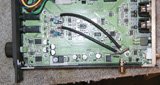
I've enjoyed this thread and actually tried the cap replacement with 6.8 uF Auricaps. The sound did improve as described. However without the "big" value caps, the bass seemed to lose focus and, oh, I guess I'll call it "compactness." So back to the bench. One of the guys in our audio club here in Phoenix modified his Shanling CD player to have a DC coupled output, so looking at the AD1853 schematic, I surmised that by making R36 adjustable (R23 on the Benchmark), the last 120mV of offset could be adjusted out. It seems to have worked. So now it's no coupling caps. The bass got compact again, very tight. But the mids and highs are even better than with the Auricaps. Smoother, more relaxed, more detail.
The pic shows the capacitor suite removed and replaced with a shorting wire, the 1k 10 turn pot in series with a 1.8K resistor in place of the 2.74K chip resistors to ground on the non-inverting side of the third opamp, a couple of series 100 ohm resistors from the opamp output to a pair RCA jacks. Although this arrangement cuts the metal cover, it also allows the normal volume controlled outputs to stay enabled.
Bill
P.S. this is my first diyaudio post! It's about time, after all I've read and enjoyed.")
I've enjoyed this thread and actually tried the cap replacement with 6.8 uF Auricaps. The sound did improve as described. However without the "big" value caps, the bass seemed to lose focus and, oh, I guess I'll call it "compactness." So back to the bench. One of the guys in our audio club here in Phoenix modified his Shanling CD player to have a DC coupled output, so looking at the AD1853 schematic, I surmised that by making R36 adjustable (R23 on the Benchmark), the last 120mV of offset could be adjusted out. It seems to have worked. So now it's no coupling caps. The bass got compact again, very tight. But the mids and highs are even better than with the Auricaps. Smoother, more relaxed, more detail.
The pic shows the capacitor suite removed and replaced with a shorting wire, the 1k 10 turn pot in series with a 1.8K resistor in place of the 2.74K chip resistors to ground on the non-inverting side of the third opamp, a couple of series 100 ohm resistors from the opamp output to a pair RCA jacks. Although this arrangement cuts the metal cover, it also allows the normal volume controlled outputs to stay enabled.
Bill
P.S. this is my first diyaudio post! It's about time, after all I've read and enjoyed.
Attachments
Hello
Thanks for the info. Some modifiers talked about a DC servo loop if for a direct connection. Is the offset stable when trimmed out once, over long time?
I have not experienced this loss of bass focus. What kind of speakers and amps do you use?
Can you post a big picture via photobucket or equivalent using the IMG button?
Hi wcwarriner.
Can you be a bit more specific on which Benchmark DAC1 you're using? There are at least 3 versions of it here (DAC1 v1, v2, and DAC1 USB). I'm using DAC1 USB.
I think your idea of using a trim pot to tune out the DC offset may be the ticket to this mod. I think Steve Nugent is probably doing the same trick in tuning out the DC offset.
I want to follow your mod, but a bigger and clearly photo is needed. Also, I am not following your entire post so it appears you're doing more to DAC1 than we're doing. I do want to drill holes or changing the design of the circuit drastically (ie: bypass some opamps, etc.)
Hi Salas,
I removed the Cerafine caps on the PSU and found there is no change in sound. So you can save your caps for other uses. I re-listened a bit tonite and it seems the loss in bass tightness is not as bad. Maybe the Auricaps do require some break-in time? I've now run them for nearly 3 days now. I'll not jump to the conclusion on the Auri's until I've at least 120 hrs of break-in.
The next thing I was thinking of doing will be changing the PSU caps to Silmic II, changing the 7805 regulator (lower noise one, any recommendation?) and the bridge rectifiers to some ultra fast soft recovery diodes.
Any suggestion on what diodes to use? What is a Hexfred diode? Any part number I should be looking at?
- Status
- This old topic is closed. If you want to reopen this topic, contact a moderator using the "Report Post" button.
- Home
- Source & Line
- Digital Line Level
- Upgrading the Benchmark DAC 1?