Why so much current? (I don't understand, and I'm curious...)
I have a lot of 5687, so that would work for me.
I will need about 5Vpk maximum output from the preamp. Since the xfmr will have a 4:1 stepdown, that means 20Vpk on the primary, correct?
If yes, then I might need more gain than a 5687 can provide. Maybe a 6DJ8 mu-follower. That can be done with 10mA plate current, maybe 12mA.
The Super Linear Cathode Follower is new to me. I'll have to look into that.
--
The more standing current the lower the impedance of the stage and also the more current available to drive the parasitics before it poops out. More is certainly better.
A SLCF with a 6DJ8 front end and a 5687 cathode follower would be good, look at the second section of the attached schematic. Its really quite simple to build point to point and the bottom valve (which functions as a CCS) can be replaced by a pentode. I built my last one using ECF86's. Allen Wright recommend a very complex power supply, but excellent performance can be achieved with a simple CLC power supply.
Shoog
Attachments
I got the Edcor XSM10K:600 line out xfmrs yesterday. They will fit inside the chassis, at the other end from the power transformer (mounted on the outside of the chassis back panel), choke and psu circuitry.
I don't think there's enough room for the four 9-pin mini tubes, separate heater supply, +20V DC supply, two 1uF output caps, and two 22uF 400V capacitors required for a stereo pair of SLCF's. I'd like to keep it to two 9-pin mini tubes/sockets. That narrows down the choices to common-cathode voltage amp with cathode follower vs. mu-follower using the low Z output to the OPT. I think I'd prefer to use the mu-follower with ultrapath-parafeed connection to the OPT, but I don't have enough knowledge to make the best-informed decision on that.
Anyway, now that I have the transformers in hand, I can start drilling holes.
--
I think I'd prefer to use the mu-follower with ultrapath-parafeed connection to the OPT,
I think that is the best choice.
Shoog
I think that is the best choice.
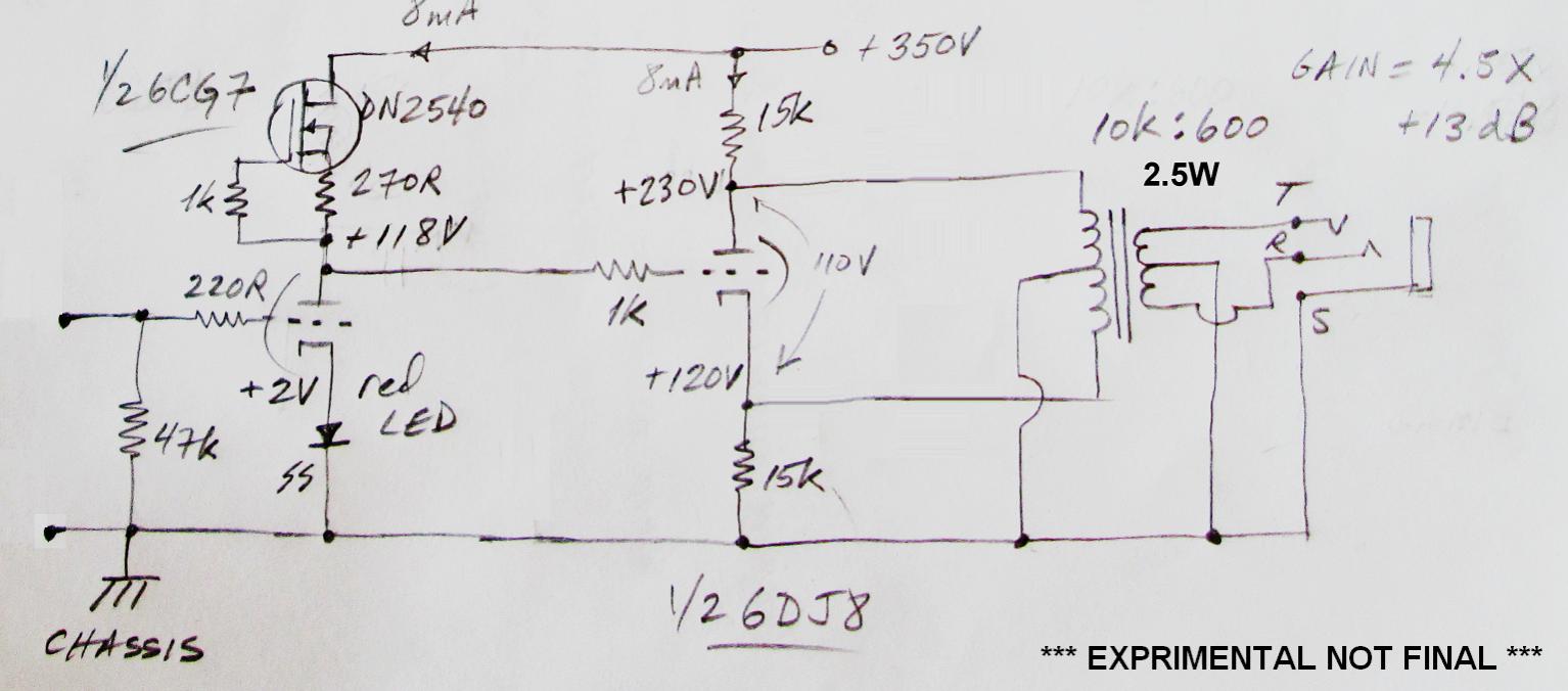
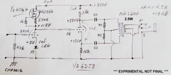
I think I'm going with it. Drilling holes this afternoon, took a break and figured I'd think about the circuit. I came up with the attached schematic. My questions...
1) How do I calculate the "ultrapath" capacitor value?
2) What's the best way to ground the OPT secondary center tap? Leave it to float and it grounds at the power amp (load) input? (In other words, connect the secondary center tap to the TRS jack's sleeve lug...)
3) I read in M. Jones VA3 that leaving the cathode resistor (Ck) unbypassed increases the rp of the mu-follower, making it more sensitive to varying loads (the lower the load resistance, the higher the distortion). Would the bottom triode benefit from LED bias? (2 of my red LED's in series would give me 4V at the bottom triode cathode.)
--
PS - I clip-leaded in a pair of Edcor WSM15K:15K to the inputs of my power amp. I'm using 47k load resistors from each secondary to secondary CT. I know it's not a great transformer, but I really like what I'm hearing. It's got bass and everything (listening to the rolling bass rumbles in Ravel's "Une Barque Sur L'Ocean" and they're coming through quite well). The triangles come through well too.
")
Attachments
Last edited:
You don't need the center tap of the secondary grounded, but it should work either way.
With the parafeed capacitor in place, then bypassing the cathode resistor makes no sense, since the parafeed provides feedback at low frequencies and those will be shunted to ground if you bypass that resistor. The parafeed capacitor needs to be large, over 100uF.
With the parafeed capacitor in place, then bypassing the cathode resistor makes no sense, since the parafeed provides feedback at low frequencies and those will be shunted to ground if you bypass that resistor. The parafeed capacitor needs to be large, over 100uF.
Thanks!
I guess I'll experiment with grounding location of the secondary CT, or floating it.
Now that may be a problem. What kind of cap do you use there? What's the necessary voltage rating? The full B+ rail (in other words, 400WVDC)? 100uF 400V in any kind of film is going to be a monster. I don't think I have room for anything like that. Is it possible to use a 100uF electrolytic and bypass it with something like a 10uF or 22uF film cap?
--
I guess I'll experiment with grounding location of the secondary CT, or floating it.
The parafeed capacitor needs to be large, over 100uF.
Now that may be a problem. What kind of cap do you use there? What's the necessary voltage rating? The full B+ rail (in other words, 400WVDC)? 100uF 400V in any kind of film is going to be a monster. I don't think I have room for anything like that. Is it possible to use a 100uF electrolytic and bypass it with something like a 10uF or 22uF film cap?
--
It needs to be rated at least 300VDC, but to be safe, use 400VDC. Generally, you have to use an electrolytic, but that's not a real problem because it only functions at low frequencies. I don't think bypassing it with a film will make any noticeable difference, so I wouldn't bother.
It's a good thing the ultrapath bypass only works at low frequencies, or that cap would be as big as the whole chassis!
Hmmm.... So definitely 400V minimum. Or higher? I could series two 330uF 300V electrolytics to get 600V, if you really think that's necessary. (I have several of those handy.) (edit to add: Or maybe not.)
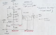
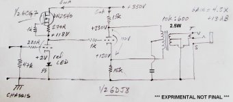
What about letting a tube do the phase splitting and using the transformer to drive the cable load and power amp inputs? A common cathode voltage amp to split-load inverter, and then the inverting and non-inverting outputs go to the top and bottom of the OPT primary. OPT secondary is balanced out. Since the signal at the primary will be push-pull, standing current in the OPT should be extremely low. It's a 2.5W rated transformer, so it shouldn't saturate (should it?).
See attachment.
--
inductive loads swing voltages higher than the rails...
Hmmm.... So definitely 400V minimum. Or higher? I could series two 330uF 300V electrolytics to get 600V, if you really think that's necessary. (I have several of those handy.) (edit to add: Or maybe not.)
What about letting a tube do the phase splitting and using the transformer to drive the cable load and power amp inputs? A common cathode voltage amp to split-load inverter, and then the inverting and non-inverting outputs go to the top and bottom of the OPT primary. OPT secondary is balanced out. Since the signal at the primary will be push-pull, standing current in the OPT should be extremely low. It's a 2.5W rated transformer, so it shouldn't saturate (should it?).
See attachment.
--
Attachments

Last edited:
it is better to err on the side of caution than be sorry later...
10ufd at 600 volts dc are not hard to find, if you are not adverse to using
motor run caps, rated for 230volt ac is more than enough...
at 10k this translates to 158volts rms primary or 39 volts secondary,
so if you are just using 2 volts rms to drive your amp,
then you have a lot of headroom to work with.
you still need a capacitor connected to the primary center tap though...
i suggest that a permanent load accross the secondary be installed, or an rc network....
10ufd at 600 volts dc are not hard to find, if you are not adverse to using
motor run caps, rated for 230volt ac is more than enough...
It's a 2.5W rated transformer
at 10k this translates to 158volts rms primary or 39 volts secondary,
so if you are just using 2 volts rms to drive your amp,
then you have a lot of headroom to work with.
you still need a capacitor connected to the primary center tap though...
i suggest that a permanent load accross the secondary be installed, or an rc network....
it is better to err on the side of caution than be sorry later...
10ufd at 600 volts dc are not hard to find, if you are not adverse to using
motor run caps, rated for 230volt ac is more than enough...
Yes, but I need 100uF, right? That's going to be difficult. Is your thinking that the transformer (inductive load) can swing double the voltage across it, so possibly up to 550 to 600V? No problem, I can use up four 330uF 300V caps and some 270k resistors to go around them. I think I have some Nichicon Muse in that value.
at 10k this translates to 158volts rms primary or 39 volts secondary, so if you are just using 2 volts rms to drive your amp,
then you have a lot of headroom to work with.
I need to read up on how to figure that. Back to the RDH4...
Output signal is hoped to be 4Vpk, or 8Vpk-pk (push-pull). Still a long way from 39V rms on the secondary.
you still need a capacitor connected to the primary center tap though...
In the first schematic (the one with the mu-follower and ultrapath-parafeed connection) the primary is single-ended (unbalanced), so no center tap used.
Were you looking at the second schematic, with the split-load inverter driving the OPT?
i suggest that a permanent load accross the secondary be installed, or an rc network....
I'll have to read up on how to implement that. If I use load resistors on the secondary, what would be a good starting point for choosing a value? Something like 10x the nominal impedance of the secondary? That would be about 5k6 or 6k2 in standard values. That seems awfully low... Maybe 47k?
The stereo power amplifier that follows has 6N6P (very similar to 5687) differential drivers as its input stage, with balanced inputs. The grid leak resistors are 220k.
--
What about letting a tube do the phase splitting and using the transformer to drive the cable load and power amp inputs? A common cathode voltage amp to split-load inverter, and then the inverting and non-inverting outputs go to the top and bottom of the OPT primary. OPT secondary is balanced out. Since the signal at the primary will be push-pull, standing current in the OPT should be extremely low. It's a 2.5W rated transformer, so it shouldn't saturate (should it?).
--
you can not just put the center tap of your output traffo to psu ground,
it will draw dc currents, the capacitor you put in will ensure that the center tap
is at ground at ac...
wrt, the traffo, i merely pointed out to you what 2.5 watt rating means,
if you require substantially lower swings,
then that means that your traffo will never be laboring at all..
maybe another member more experienced than me will chime in...
tbh, i am not even sure that you need to ground that center tap...
maybe just a single cap in series with the primary is all that is needed...
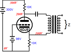
Morgan Jones describes a push-pull cathode follower output stage using 6AS7 tubes in Valve Amplifiers 3rd Ed (page 391, fig 6.9).
Broskie has this graphic, showing how to bias a PP CF output stage...
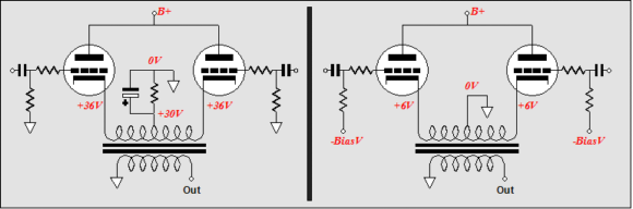
I don't have the understanding to analyze how that would translate to a split-load inverter's outputs going into the center-tapped primary of an output transformer.
Perhaps if the split-load inverter's outputs were capacitor-coupled to the primary? (As in parafeed, but push-pull?)
I'm probably missing something elementary. I often am...
--
Maybe something like an RC network from each split-load inverter output to primary CT is what needs to happen (see attached schematic)
--
...And then, maybe all that's needed is a capacitor in series from ground to the primary CT to block DC. Is that what you were suggesting? (I might not understand what you meant. That's pretty likely, actually...)
--
Broskie has this graphic, showing how to bias a PP CF output stage...
I don't have the understanding to analyze how that would translate to a split-load inverter's outputs going into the center-tapped primary of an output transformer.
Perhaps if the split-load inverter's outputs were capacitor-coupled to the primary? (As in parafeed, but push-pull?)
I'm probably missing something elementary. I often am...
--
Maybe something like an RC network from each split-load inverter output to primary CT is what needs to happen (see attached schematic)
--
...And then, maybe all that's needed is a capacitor in series from ground to the primary CT to block DC. Is that what you were suggesting? (I might not understand what you meant. That's pretty likely, actually...)
--
Attachments
Last edited:
still think that just one cap C1 is all that may be required....
Broskie's drawings convey a different meaning wrt your idea...
do you have this circuit on breadboard?
you may want to try a cap from center tap to psu ground,
it can be a polarized ecap since the center tap is at positive
potential wrt psu ground, or a film cap in series with the traffo primary,
you can try it both ways and find out what happens...
maybe someone can run simulations on your circuit...
Maybe this is all that's needed -- a capacitor to block DC from ground to the OPT primary CT (see attached).
--
yes, you can try that...
If you're using an output transformer, you wouldn't even need the split-load phase inverter at all to do balanced output, especially if you're cap coupling or parafeeding to the transformer in the circuit.
It will still draw current through the primary from the plate end to the cathode end. Depending on the DCR of the winding, it will act like a small value resistor connecting from the plate to the cathode and throws off everything.
Maybe this is all that's needed -- a capacitor to block DC from ground to the OPT primary CT (see attached).
It will still draw current through the primary from the plate end to the cathode end. Depending on the DCR of the winding, it will act like a small value resistor connecting from the plate to the cathode and throws off everything.
Why do you want to ground the centre taps at all? A balancing transformer should have no ground connection on its secondary, otherwise it's not guarenteed to be balanced. And in this case there is no need to ground the primary centre tap either. Some sort of secondary load is a good idea, and often it is a Zobel network.
Last edited:
- Status
- This old topic is closed. If you want to reopen this topic, contact a moderator using the "Report Post" button.
- Home
- Amplifiers
- Tubes / Valves
- Unbalanced In > Balanced Out line amp - How To Do It?