All these line amp questions today! Coincidentally, I need to put together a tube line amp with the following features:
1) Unbalanced input (for consumer audio sources like CD players)
2) Balanced output to drive a tube amp with balanced input to a LTP stage (about 200k input resistance). The power amp needs about 5 volts of signal to be driven to full output.
3) The gain of this line amp needs to be about 6X. 10X would be OK, but is a bit too much.
4) The line amp will be driving about a meter of balanced interconnect.
I keep going back and forth between a 5687 LTP with RC-coupled outputs (about 1k8 output resistance) or something like the Impasse but with less gain (for a much lower output resistance).
If the 5687 LTP has decent enough drive capability for only a meter of balanced interconnect, then I guess that would be the winner. I attached an old schematic from Artosalo, of a 6N6P LTP line amp. (It looks like a Schmitt inverter to me.) I'd use a negative supply for the tail CCS and direct-couple the inputs, but otherwise that's the idea.
If the Impasse topology is the better way to go:
I could make the first stage a triode-wired 4P1L. It has the right mu and good linearity for the job. It also works well at low plate voltages, making it much easier to DC-couple the two stages, but I don't want to spend buckets of money on getting the proper current-regulated DC to the filamentary cathode. But then again, the 4P1L is a perfect candidate for 'filament bias', which makes it very attractive. I've never done that before.
I could use a 6V6-triode for the first stage, and then I'd need to choose the best tube for the cathodyne output stage. It would still be RC-coupled. 6DJ8? Or is higher transconductance or mu needed for this job?
I could bite the bullet and shell out for a pair of proper output transformers. But is that really necessary to drive only a few feet of cable into a high impedance load?
Thanks for any advice.
--
Attachments


Last edited:
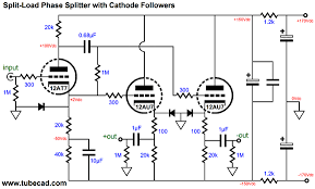
I would think the cathodyne version has greater flexibility, and no input cap needed, but has the disadvantage of dissimilar output impedances which is not really what you want for balanced transmission, although domestic conditions are admittedly more relaxed. But you could easily buffer its outputs with DC coupled MOSFETs or cathode followers. http://www.tubecad.com/2008/02/blog0135.htm
There are loads of other SE to balanced ideas on tubecad.com
There are loads of other SE to balanced ideas on tubecad.com
Last edited:
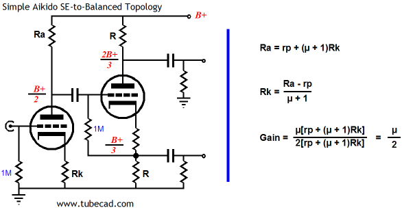
I would think the cathodyne version has greater flexibility, and no input cap needed, but has the disadvantage of dissimilar output impedances which is not really what you want for balanced transmission, although domestic conditions are admittedly more relaxed. But you could easily buffer its outputs with DC coupled MOSFETs or cathode followers. Aikido Single-Ended-to-Balanced Topology
It looks like there's a complete schematic in that article, ready to go.
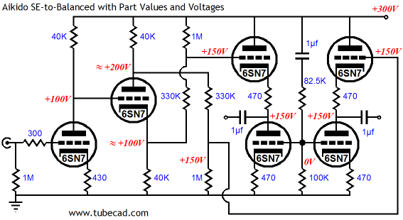
It would make quite the Wall Of 6SN7's, what with 3 of them per side. Come to think of it, that's an awful lot of heater current...
Broskie version of cathodyne output line amp:
Broskie only mentions unequal Zo in the case of using only one output (unbalanced out).
"Now this simple circuit works quite well in a push-pull power amplifier, but it does not succeed so well as a single-ended-to-balanced converter for line stage use, as we cannot just use one output at time without unbalancing the phase splitter and without incurring the poor PSRR noise penalty."
I don't actually need to switch between balanced and unbalanced output with this one. I can't see where I'd be using the split load/cathodyne/concertina stage with only one output loaded.
An LTP could also have cathode followers or source followers fitted. The question I still have is if that is necessary, given that the Zout of this LTP is about 2k ohms, used into a large (ca. 200k) load, with only about 3 feet of interconnect.
For the LTP, I was thinking of what's in the attached schematic, which gets rid of the input caps. Maybe I'd add cathode followers on the outputs, but again, the question is whether that would actually be necessary.
thanks.
Attachments

Last edited:
So I went and read some of John Broskie's writings about Aikido, etc.
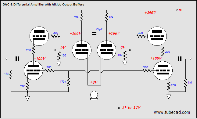
I found something very interesting about diff pairs, in "Balanced-Ouput DACs & Differential Amplifiers".
Balanced-Ouput DACs and Tubes and Aikido
In there, he says:
JB goes on to recommend adding an Aikido output stage to cancel all that power supply noise.
____________________________________
But don't the above statements about the differential pair's alleged lack of PSRR directly contradict what Morgan Jones writes in "Valve Amplifiers"? On page 138 of the 4th Ed, under "Power Supply Rejection Ratio (PSRR)":
Table 2.2 Comparison of PSRR for Different Topologies shows PSRR of a common cathode stage, mu-follower and differential pair. He shows the maximum PSRR of a diff pair to be 62dB, but elsewhere states that 40dB is the usually realized figure in practice. Still, with a reasonably quiet power supply, PSRR = 40dB should be good for a line stage.
______________________________________
So who's right here? Or (as is most likely), what am I missing?
--
I found something very interesting about diff pairs, in "Balanced-Ouput DACs & Differential Amplifiers".
Balanced-Ouput DACs and Tubes and Aikido
In there, he says:
"The differential amplifier suffers from a horrible PSRR figure... The large-valued common cathode resistor (or... active constant-current source) that made the great CMRR possible also reduces the PSRR to nearly zero."
JB goes on to recommend adding an Aikido output stage to cancel all that power supply noise.
____________________________________
But don't the above statements about the differential pair's alleged lack of PSRR directly contradict what Morgan Jones writes in "Valve Amplifiers"? On page 138 of the 4th Ed, under "Power Supply Rejection Ratio (PSRR)":
"Since hum and noise on the power supply line are a common-mode signal, they must also be attenuated by the CMRR."
Table 2.2 Comparison of PSRR for Different Topologies shows PSRR of a common cathode stage, mu-follower and differential pair. He shows the maximum PSRR of a diff pair to be 62dB, but elsewhere states that 40dB is the usually realized figure in practice. Still, with a reasonably quiet power supply, PSRR = 40dB should be good for a line stage.
______________________________________
So who's right here? Or (as is most likely), what am I missing?
--
but power supply noise is a common mode signal, as far as the NEXT differential stage is concerned
To clarify what I mean, the PSRR is only bad when you break the differential topology.
Thanks, I wasn't sure about that. Since this line preamp is meant to be unbalanced-input/balanced-output, feeding a push-pull power amp with balanced inputs, then the PSRR gained by the LTP/diff would be carried all the way to the output transformer. That sounds like a good thing to me.
parafeed output transformer
I would suggest any single ended line stage with enough voltage gain, driving a 4:1 step down transformer in parafeed arrangement would be suitable for your application and involve the least amount of headaches. Jensen came up with this design a long time ago. There are ways to improve it.
I would suggest any single ended line stage with enough voltage gain, driving a 4:1 step down transformer in parafeed arrangement would be suitable for your application and involve the least amount of headaches. Jensen came up with this design a long time ago. There are ways to improve it.
Attachments

Thanks, I'm sure that would be good. Unfortunately, according to the price sheet, that JT-10K61-1M output xfmr is $137 each. That would be almost $300 for a pair, all in.
How about something from the Mosfet Follies? I've attached a schematic of an idea. I checked it as best I could, but it probably has mistakes and misconceptions. This kind of thing should drive the cable capacitance with no worries, right? (Sorry for the sloppy schematic.)
--
How about something from the Mosfet Follies? I've attached a schematic of an idea. I checked it as best I could, but it probably has mistakes and misconceptions. This kind of thing should drive the cable capacitance with no worries, right? (Sorry for the sloppy schematic.)
--
Attachments

Last edited:
You can use any of a number of other 4:1 output transformers, starting at $46 each from Cine Mag.
As for your schematic, I'd suggest simulating it least first, before building it.
As for your schematic, I'd suggest simulating it least first, before building it.
You can use any of a number of other 4:1 output transformers, starting at $46 each from Cine Mag.
As for your schematic, I'd suggest simulating it least first, before building it.
Re: Cinemag transformer, did you mean the CM-2810?
If I have a single-ended gain stage with gain of 24X, would a 4:1 transformer step that down to voltage gain of 6X?
As for output impedance, if a 6DJ8 is used, with rp of about 3k2, then the output Z from the transformer secondary would be 800R?
thanks
Yeah, those are the ones. Of course, some people here like the really cheap Edco transformers, but I would not recommend them.
Yeah, the drop is 12 dB in gain.
The output Z should be 200 ohms in your example, if the 6DJ8 has the transformer primary as the load (in which case you can't use the Cine Mag transformer - you need one gapped for single ended operation).
Np/Ns = SQRT(Zp/Zs)
Ah, so that transformer needs a balanced signal to its primary? That's not difficult. Or...
Does the primary need to be fed AC signal only, as in capacitor-coupled from the plate of the common-cathode gain stage?
I suppose I need to look at those Jensen application notes....
--
Does the primary need to be fed AC signal only, as in capacitor-coupled from the plate of the common-cathode gain stage?
I suppose I need to look at those Jensen application notes....
--
That's a White Cathode follower on the output, right? jensen calls it a 'Cascode Follower'?I would suggest any single ended line stage with enough voltage gain, driving a 4:1 step down transformer in parafeed arrangement would be suitable for your application and involve the least amount of headaches. Jensen came up with this design a long time ago. There are ways to improve it.
And would it be better to use a triode in the first stage. Then reduce the amount of NFB.
Ah, so that transformer needs a balanced signal to its primary? That's not difficult. Or...
Does the primary need to be fed AC signal only, as in capacitor-coupled from the plate of the common-cathode gain stage?
I suppose I need to look at those Jensen application notes....
--
Not necessarily. The Jensen schematic I posted uses parafeed (capacitor coupling to the transformer). The type of transformers that Jensen, Cine Mag, etc. generally sell cannot function very well with any DC current on either the primary or the secondary. Many manufacturers make transformers that allow DC, but you have to specify how much current because the gap they use is different for different DC current levels. Generally, a transformer made for single ended use that has a gap for DC is going to be larger and more expensive than one that can only handle AC. So, it is more economical to use the parafeed technique than to use the DC coupled technique.
As for push-pull service, the transformer needs a center tap (or independent primaries) and the ability to handle a small amount of DC offset (which is often specified). There are manufacturers like Sowter and others who make small signal push pull output transformers for line level use. They are generally not inexpensive, though they should be less expensive than the single ended transformers that allow DC.
That's a White Cathode follower on the output, right? jensen calls it a 'Cascode Follower'?
And would it be better to use a triode in the first stage. Then reduce the amount of NFB.
Yes, it is a White Follower, which is an excellent driver in my opinion.
I have no opinion about triode vs. pentode and large amounts of feedback vs. less amounts. All I know is that in single ended operation, both pentodes and triodes have the second harmonic dominant in their distortion spectrums, so they should sound equally sweet to the ear, though the degree of sweetness may be different depending on topology and specific tube type selection.
I don't want to start a war here but as long as a cathodyne is equally loaded at both terminals then the output impedance at anode and cathode is approx. 1/gm. This counter-intuitive result is because it is necessary to consider both outputs at once rather than simply making an analysis of anode and cathode conditions separately. The maths is straightforward and can be found in various places .
The cathodyne is an excellent and simple phase inverter.
The cathodyne is an excellent and simple phase inverter.

- Status
- Not open for further replies.
- Home
- Amplifiers
- Tubes / Valves
- Unbalanced In > Balanced Out line amp - How To Do It?