Rongon, If you use a cathodyne PLUS an output transformer my guess is that you would be able to drive computer speakers.
Rongon, If you use a cathodyne PLUS an output transformer my guess is that you would be able to drive computer speakers.
Or headphones!
I'm leaning toward using stuff I have around already.
I'd use a Russian 6P1P (9-pin 6V6 or 6AQ5 equivalent) in triode, as my gain stage. Gain of about 7. I'd copy Salas' idea for a 6V6-triode line amp. Everybody says it sounds great, so why not. It requires 20mA of plate current, but what the heck, ya only live once... Then, I guess I could use that 6J9P-triode as the cathodyne, with 15mA going through it. I figure the output Z would be about 60R or so.
It would wind up being an incredibly wasteful, power-hungry version of SY's Impasse preamp.
Thank you diyAudio!
--
Sometimes you just have to juice it up to get what you want... otherwise you'd be playing with Class D amps...
Rongon, without considering the DC resistance of the transformer secondary the output impedance will be 1/gm x 1/16, i.e., several ohms
Transformer input?
It's taken me a while, but I'm seeing why this could be a good way to go.
If I put an input transformer at the inputs of the power amp, that will increase the gain of the LTP phase splitter/driver, by taking away the need for it to split phase. So the amp becomes:
(unbal in) INPUT XFMR (bal out) -> PP DRIVER -> PP OUTPUT STAGE -> OPT
Being that I don't know much at all about the deep mysteries of electromagnetic devices, how do I specify what the input transformer needs to be?
I know there will be three program sources:
- an RIAA preamp with an output resistance of about 2k ohms
- a commercial CD player, with typical low output impedance
- a run-of-the-mill 1980's tuner
Those go to a selector switch and an Intact Audio inductive attenuator. The output from the attenuator goes to the input of a simple common cathode triode preamp (6N6P), with an output impedance that's probably pretty high (unbypassed cathode resistor).
I noticed that there are several 1:1+1 transformers available, with nominal impedances of 10k:10k, or 15k:15k. I was looking at some from Edcor, either https://www.edcorusa.com/wsm15k-15k or the more deluxe https://www.edcorusa.com/xs4400 (configurable as a 1:2 or 1:3 step-up).
The cheaper 1:1 version has a pretty response curve, but is that at only +1dBu?
The main question is, am I on the right track with choosing an input xfmr to act as the phase splitter? Or does the primary impedance need to match the (lower) source impedance, and the secondary match the much higher impedance of the tube stage? Or is there a high likelihood of adverse interactions between an inductive attenuator going straight to a 1:1+1 input transformer?
--
Questions re: Input transformer as phase splitter for PP amp
I hope I'm not being a pest, but I can't find definitive answers to my newbie questions. I hope somebody's willing to point me in the right direction.
I want to get a balanced signal to my power amp (PP 2A3's, 6N6P LTP driver, just the two stages). My first thought was that I'd make a preamp with balanced outputs, but that will guarantee that I'll have too much gain. (Common problem.) Then dirkwright and others suggested I use transformers to split phase. I've found the best place to do that is at the input of the power amp instead of at the output of the preamp.
So I went looking for input transformers for tube amps. I've found some info on the Lundahl site, and it looks like the LL1690 is what I'd want to use there. But it's really pricey. Since it's a 1+1:1+1 'high impedance, high level' transformer, I figure Edcor has something similar. They have a couple of 15k:15k line transformers, one of which is the XSM15K-15K.
If I use that one, how would I wire it into my amp's inputs? I whipped up a schematic showing what I think is the way to do it.
Is the 1+1:1+1 input xfmr made to work as a 2:1+1 the way I have it shown?
Rp1 and Rp2 are the load resistors. How do I figure what values to put there? Would I need to do that empirically, putting a square wave in and adjusting for best looking waveform on a scope?
Rs1 and Rs2 are the grid stoppers for the LTP stage. Would those still be desirable with a transformer-coupled input?
Thanks for any pointers. I'm completely out of my element here...
Attachments

How much are you willing to spend on this? Jensen, Cine Mag, Sowter, Lundahl, etc. all make fine high impedance 1:1 input transformers. You don't need a center tap on the transformer secondary, so you can use a normal input transformer. A 10k:10k input type should be fine for your application.
It looks like there's a complete schematic in that article, ready to go.
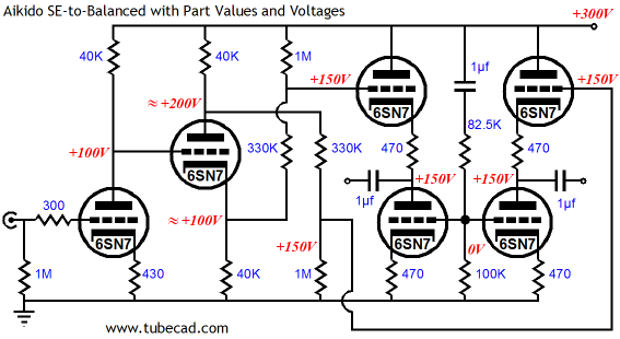
Intriguing circuit, brilliant even. I like the direct coupling between stages. My question is wouldn't the voltage divider of 1M & 330K also divides the AC and lose some gain before going to the cathode followers? Doesn't seem like Broskie addresses that in the article. Maybe I missed it. If the gain is lost, can I add coupling caps paralleling with 330K resistor to recover the gain?
wouldn't the voltage divider of 1M & 330K also divides the AC and lose some gain before going to the cathode followers?
If the gain is lost, can I add coupling caps paralleling with 330K resistor to recover the gain?
Yes it will, and yes you can, but it will spoil the hum-cancelling ratios in the design, unless you altered some other stuff too.
Gain is always excessive in line amps so no doubt the AC attenuation was entirely deliberate. If you need more gain then change the front end valves or add an extra stage.
Shoog
Shoog
I don't think a 10k:10k input bridging transformer is suitable for the output of a line amp, though. Meant to be the input transformer on the power amp, right? (No air gap, so no quiescent current allowed on the primary, unless used parafeed, but that has been discussed previously...)
Here's a question -- What's the easiest pri/sec ratio for getting the best transformer transfer behavior? I hear that in an output transformer, a lower primary impedance means it's easier to get wide bandwidth, high inductance with low leakage inductance and interwinding capacitance. Conversely, it's harder to get that kind of performance as the primary impedance goes up.
Following that logic, is it easiest to get good performance from a 1:1 pri to sec ratio, or is easier to get good performance from a step-down transformer (like maybe 2:1 or 4:1, primary to secondary)?
Since gain is easy to get, a 4:1 transformer would be pretty nice. Use a really linear tube with about 25X gain, and get about 6X gain after the step-down.
But if a 1:1 transformer is going to be superior (all things being equal, of course), then never mind.
--
Last edited:
Step down is always going to perform better if you can burn some gain up - and for all the reasons you mentioned. Basically the more wire needed for higher impedance ratios, the more strays present and the more expensive the winding techniques to avoid them.
You can get very good performance from cheap power toroidals as outputs in line stages if you can drive them with a few hundred ohms of output impedance and a step down ratio. Similar performance from a high impedance output tube will cost much much more to buy.
Shoog
You can get very good performance from cheap power toroidals as outputs in line stages if you can drive them with a few hundred ohms of output impedance and a step down ratio. Similar performance from a high impedance output tube will cost much much more to buy.
Shoog
If I use something like a triode wired 6e5P, I can get the Zout to maybe 1000 ohms, with something like 25X gain. Put that into a 4:1 stepdown transformer, and I'd be getting somewhere. However, that transformer would need to be able to take 15mA or more of standing current on its primary. Air gap required, and now we're right back to a bigger, more expensive transformer, aren't we?
If I use a cathode follower to get a much lower Zout, then there's still the problem of standing current on the OPT primary, so the transformer still needs an air gap. Unless you know something about using a power toroid that I could learn from... If not, I'm right back to the cathodyne (concertina) output stage.
If I go with parafeed, then there's that capacitor in the signal path, in addition to the transformer. I don't think I want to go that way, so I'd be right back to a cathodyne output stage.
An input transformer on the power amp is making more and more sense. No need for an air gap, as there's no quiescent current through the primary. Something like Lundahl LL1540 or Jensen JT11P-1 would work. I'll have to see if there's a stepdown version of those.
--
I'm preparing an old chassis for an experimental line stage with cathodyne output. I think the input gain stage will be a 6CG7 or 6GU7, and the output will be a 6DJ8 cathodyne. Something like SY's Impasse, but without the input transformer (for now, at least). I have a Thordarson 650VCT 40mA power transformer that should do nicely. It also has 5V 2A and 6.3VCT 2A windings.
--
The way i have and would do it is with a LTP driving a PP output transformer which can be setup for zero standing current. Its surprisingly simple and produces a good result. Using a wilson current mirror is the best way to go but requires a cathode to cathode bypass with a large electro-cap.
An output impedance of 1000R places you into the expensive range since you need the transformer to be at least 4000R to get adequate loading. Here a 10K:10K transformer looks sensible, but to get 10K:10K+10K is even more expensive again.
There are no free lunches, but if i were you I would fight my phobia about parafeed caps and go the easy way. personally i think the ill's of a parafeed cap are far smaller than a gapped transformer unless you are going for that classic SE sound.
My candidate for this job would have to be the 5687 into a step down of 4:1+1 giving a gain of about 2x overall.
Shoog
Last edited:
OK, understood, and thanks.
5687 into 4:1+1 would be great. Would Jensen JT-6110-KB be the sort of OPT you're thinking of? Or something much cheaper?
A common cathode 5687 would have Zout of about 2k. (Maybe lower, I'm being cautious.) Did you mean a single 5687 per side, with one half as a cathode follower? That should get the Zout down to <200R.
Finally, wouldn't an input bridging transformer at the input of the power amp be more effective than an OPT on the line stage? (The OPT version would have to drive the 1.5m of interconnects and the input capacitance of the power amp. An input xfmr on the power amp would have just a few cm of wires from its secondary to the amp input grids, with whatever load resistors are necessary.)
--
Mr. Yaniger's preamp for the Pass F4 was unbal in bal out (You can eliminate the input transformer)
An externally hosted image should be here but it was not working when we last tested it.
- Status
- Not open for further replies.
- Home
- Amplifiers
- Tubes / Valves
- Unbalanced In > Balanced Out line amp - How To Do It?