…...after having some days ago big differences between the gate voltages for the SJ and SK (1.3A and zero offset), 11.9V and 8.3V means 3.6V difference,
http://www.diyaudio.com/forums/pass...f-sit-beast-thousand-psus-19.html#post3680875
I looked for a better pair and I have now 8.3V and 9.2V at the gates.
So difference is only 0.9V, of course worse than Nelsons 0.6V value. He is the Matching King!
But maybe this is not important for the sound, only for measuring freaks, who knows at the moment…….
I replaced the gate voltages supply by batteries…. still the hum.
So I can say hum is from the main PSU, needs to be regulated (Nelson!) or cap multiplied,
or may Edcor has has a very bad place…. normally these 600:600 are not so susceptible but…..
Good and not so difficult to make PowerReg:
Introducing the PowerReg - pink fish media
Used succesfully in MHouston's ZCA Mosfet class A amp. Zero noise.
Mini Autograph 2:3 with Audio Nirvana Super 10: Satchmo. - YouTube
Hope this helps.
Good luck,
M.
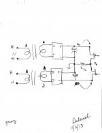
Hello generg. The attached schematic shows a PSU; dual primaries, dual secondaries and dual bridge rectifiers. The ripple is shown as a half shaded AC signal on the power rails; but maybe sawtooth in shape. Note the relative phase of the 4 transformer windings [triangle]. In an ideal world, the magnitude or amplitude of the ripple at the power rails are equal, but their phase on one rail is inverted relative to the other. It follows that both ripple signals flow through the SITs and wipe out at Vo. Residual ripple due to unequal amplitudes at the rails will flow through Zl and will be heard.I replaced the gate voltages supply by batteries…. still the hum.
So I can say hum is from the main PSU, needs to be regulated (Nelson!) or cap multiplied,
or may Edcor has has a very bad place…. normally these 600:600 are not so susceptible but…..
Attachments
Hello generg. The attached schematic shows a PSU; dual primaries, dual secondaries and dual bridge rectifiers. The ripple is shown as a half shaded AC signal on the power rails; but maybe sawtooth in shape. Note the relative phase of the 4 transformer windings [triangle]. In an ideal world, the magnitude or amplitude of the ripple at the power rails are equal, but their phase on one rail is inverted relative to the other. It follows that both ripple signals flow through the SITs and wipe out at Vo. Residual ripple due to unequal amplitudes at the rails will flow through Zl and will be heard.
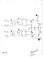
My picture in the above post was not clear. Here is a replacement with big ripples on the rails. With an AC voltmeter [e.g. Fluke etc..] measure the ripple voltage relative to common, and as an example get 1V for either power rail. Next measure the ripple rail to rail. A reading of 2 V means the ripples are out of phase [right answer]. A reading close to zero means the ripples at both rails are in phase. In this case reverse the absolute phase of one secondary winding to its bridge rectifier. With AC voltmeter measure residual hum Vo to common.
Attachments
some postings back I wrote….
"There is one SJ28 KF instead of KE but it is not outside…….
As far as I remember the KE and KF was a pinch Off voltage and this marking seems not very important for the matching of Iron AmP or the SONY AmP….."
i wrote this because the one KF I had was embedded in the KE lines…
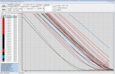
But the SK82 KD I used for Mikes L´Amp clearly needs lower gate voltage for the same drain current….
So the classes are important, sorry…only the one KF seems not to behave correct….
in the picture the two left curves are the KD….!
"There is one SJ28 KF instead of KE but it is not outside…….
As far as I remember the KE and KF was a pinch Off voltage and this marking seems not very important for the matching of Iron AmP or the SONY AmP….."
i wrote this because the one KF I had was embedded in the KE lines…
But the SK82 KD I used for Mikes L´Amp clearly needs lower gate voltage for the same drain current….
So the classes are important, sorry…only the one KF seems not to behave correct….
in the picture the two left curves are the KD….!
Attachments
as I told the one KF was embedded in the KEs….
but the KDs are really apart….
best to wait for Nelsons writing….
what I do not know when the SITs are very separated I can of course adjust never the less the 1.3A and zero offset. They have of course very different gate voltages. So in DC terms all is good.
But the curves start at very different points and may have different inclinations (transconductance) so I thing AC wise there might be a mismatch resulting in higher distortion.
Is this assumption correct? All answers welcome….

I think it's OK to use different ranks for the N and P ch, you just have to
have different bias voltages. For example, the devices I used in the amp
at BAF had the same rank, but their bias voltages were 8.8V and 12.0V.
Oh, I believed in the values shown with the beamer at BAF, that were much closer.....
Thanks for commenting!
@ZM when I have nothing to do I prefer to complicate things.....
I replaced the gate voltages supply by batteries…. still the hum.
So I can say hum is from the main PSU, needs to be regulated (Nelson!) or cap multiplied,
or may Edcor has has a very bad place…. normally these 600:600 are not so susceptible but…..
generg. Is your output test circuit wired exactly as shown in post #4? The AC impedance of the bias batteries shown in the schematic is practically zero Ohms. Thus, ripple e.g. at the +23 V rail appears almost intact in amplitude and phase at the gate of the SIT. The ripple signal between gate and source is equal to zero V and so the SIT will not pass ripple to show at the output; to be heard.
Oh, I have typed it wrong here.
My transistors are JF-33, not KE-33.
If I want to use them in this project, what things should I need to pay attention to please ? Will the sound quality be affected ?
Thanks again.
Sidney
JF...? Never seen before....where did you get them from? But you see Nelson's comment.......
..
@ZM when I have nothing to do I prefer to complicate things.....
as known , Mighty ZM is leader in that field - unnecessary complicating Papa's (brushed ) perfect simple solutions

- Status
- This old topic is closed. If you want to reopen this topic, contact a moderator using the "Report Post" button.
- Home
- Amplifiers
- Pass Labs
- Ultrasimple SIT PP amp from BAF , or SIT Beast with a Thousand PSUs