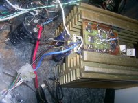
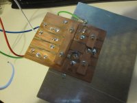
Heres my 150W Mos-Fet Monoblock. The other one is "similar"
An externally hosted image should be here but it was not working when we last tested it.
Your TOSHIBA's are fakes.
Prototyping with fakesNot?

Yeah, I know it. These are genuine fakes!
So, used with a lower power supply. This way fakes can survive if you don´t have originals and don´t abuse.
After all, it was my first DIY. "Let´s do it and see what happens".
Wooden plate, fake too
Borrowed from my wife... a sort of kitchen table.
Without practice in placing amplifier parts, at that time, a good way to experiment without ruining an expensive metal case.
Earlier today this was only ugly, but now it is working as well so I can revive this old thread
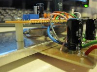
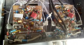
It is only a prototype, I wanted to experiment with a 'the Wire' type design but with Exicon TO3 MOSFETs. The TO3 devices aren't very prototype friendly without a good etching setup and the LME49830 certainly isn't, the legs were just about long enough to splay out like this if I didn't solder the NC pins!
It was unstable earlier, oscillating very strongly at 800kHz or so. Here's a few things to be careful with:
Now it is operational but I will optimise by experimenting with gate stopper values (currently 150R) and compensation (currently 33pF). unmatched gate stopper values may help as used in the Wire design, to get over the differing P and N channel input capacitance, or alternatively extra capacitance added to the N channel since these are relatively low capacitance MSOFETs to start with.
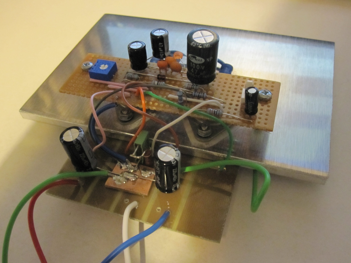
EDIT: added extra photo as the LME49830 was barely visible. It is soldered on the reverse of the stripboard, surface mount style. May require a heatsink when I use higher voltages.
It is only a prototype, I wanted to experiment with a 'the Wire' type design but with Exicon TO3 MOSFETs. The TO3 devices aren't very prototype friendly without a good etching setup and the LME49830 certainly isn't, the legs were just about long enough to splay out like this if I didn't solder the NC pins!
It was unstable earlier, oscillating very strongly at 800kHz or so. Here's a few things to be careful with:
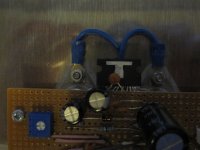
- Space the input and output (feedback points) well apart, ideally with grounded area between them. This was, I believe, the main issue I had
- Put gate stoppers close to the MOSFETs
- Make the compensation capacitor connection short. Here it is soldered across the IC pins, I broke the track behind the comp pin to reduce extraneous pickup as well
- Ensure the 'heatsink' is grounded. Leaving it floating I could initiate oscillation in an otherwise stable design by touching it at the same time as the input connection
Now it is operational but I will optimise by experimenting with gate stopper values (currently 150R) and compensation (currently 33pF). unmatched gate stopper values may help as used in the Wire design, to get over the differing P and N channel input capacitance, or alternatively extra capacitance added to the N channel since these are relatively low capacitance MSOFETs to start with.
EDIT: added extra photo as the LME49830 was barely visible. It is soldered on the reverse of the stripboard, surface mount style. May require a heatsink when I use higher voltages.
Attachments

Last edited:
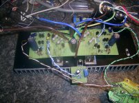
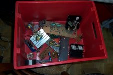
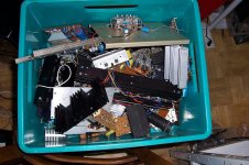
You're just a bunch of amateurs: this is what ugly means (it's just the beginning: at this stage, the rest of the material would probably be censored, I'll post it later, when the world is ready)
Attachments
Hi Elvee
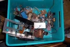
I think we all have a bin of old experiments and projects of past days. Yours looks like they are still complete, functional? Vero board is so handy for 'experiments' conceived in feeble confidence that does not warrant spending money to have a PCB manufactured. As for my ugly bin, projects such as this one end up having key parts removed and reused in newer 'experiments', such as the three THAT 340 matched transistor arrays (~$8.00ea) that were 'recycled'.
I think we all have a bin of old experiments and projects of past days. Yours looks like they are still complete, functional?
Vero board is so handy for 'experiments' conceived in feeble confidence that does not warrant spending money to have a PCB manufactured. As for my ugly bin, projects such as this one end up having key parts removed and reused in newer 'experiments', such as the three THAT 340 matched transistor arrays (~$8.00ea) that were 'recycled'.As long as an amplifier works,Earlier today this was only ugly, but now it is working as well so I can revive this old thread
It is only a prototype, I wanted to experiment with a 'the Wire' type design but with Exicon TO3 MOSFETs. The TO3 devices aren't very prototype friendly without a good etching setup and the LME49830 certainly isn't, the legs were just about long enough to splay out like this if I didn't solder the NC pins!
EDIT: added extra photo as the LME49830 was barely visible. It is soldered on the reverse of the stripboard, surface mount style. May require a heatsink when I use higher voltages.
we can always later make it more beautiful.
Almost everyone has built some ugly version of amplifier.
Nice to see your pictures!
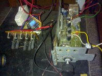
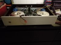
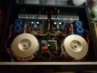
Do my amplifiers (main amplifier and preamplifier) qualify? Both were good enough for a publication in Electronics World, but I didn't dare to send them any photos.
It's a pity I didn't take any photos of my high-voltage amplifier. It was simply a wooden drawer with large perfboards in it.
It's a pity I didn't take any photos of my high-voltage amplifier. It was simply a wooden drawer with large perfboards in it.
Attachments
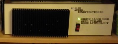
Do my amplifiers (main amplifier and preamplifier) qualify?
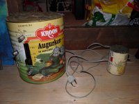
What's the little can on the right, the remote control ?
That was very uglyDo my amplifiers (main amplifier and preamplifier) qualify? Both were good enough for a publication in Electronics World, but I didn't dare to send them any photos.
It's a pity I didn't take any photos of my high-voltage amplifier. It was simply a wooden drawer with large perfboards in it.
But I have no doubt it works well.
- Home
- Amplifiers
- Solid State
- UGLY Looking Amp! - but good working