Audio Research 150.2
The only picture of the inside I've found is in a
previous post,
but it is 150.2. The 300.2 would have the same Tripath TA0105A, as the chip is rated 500W 4ohm 300W 8ohm. If you want one 300.2 look here.
If you understand something about design solutions and parts used in 150.2, please let me know: amp and PS boards are their original design.
Ciao
Thomas
KBK said:
I'll have to get a look inside one, if I can. Buy one, take it apart. Unless someone knows of a place for detailed photos of the innards???
The only picture of the inside I've found is in a
previous post,
but it is 150.2. The 300.2 would have the same Tripath TA0105A, as the chip is rated 500W 4ohm 300W 8ohm. If you want one 300.2 look here.
If you understand something about design solutions and parts used in 150.2, please let me know: amp and PS boards are their original design.
Ciao
Thomas
That's an interesting tidbit to know. I've wound cores with 1mm wire and like I said, it just takes some more brute force. 0.5mm wire feels like wet spaghetti to me anymorenoah katz said:As a point of interest, you might like to know that doubling the diameter increases the bending stiffness 8X.
")
I found something online that described the technique I posted pictures about that called it mobuis winding. I have since searched more with 'mobius winding' as the keywords and have come about a lot more hits and information regarding the method you are describing for winding self supporting coils. It seems I may be misiformed by calling the method I described 'mobius winding' but I have no idea what else you would call it. Odd-even winding? It doesn't seem to have any advantages for single inductors but may be more useful for coupled inductors or transformer windings.Pjotr said:The mobius winding technique is one of them but what I remember from college is that this technique consist of placing one or two turns along the whole width of the coil and going back and forth the width of the coil each next turn: Like the way self supporting HF coils are wound, giving the coil a “braided” appearance.
If you were to use strands of Litz wire instead of a single wire, wouldn't it be more beneficial to have all the Litz strands laying side by side close to the core instead of having them all twisted together to form a psuedo wire that is then wound around the core?Pjotr said:Still the best way to wound optimum toriode coils is to use a large enough toroide to wound one single layer with evenly spaced turns along the full circumference and with some airspace between each turn. And to raise Q further you will need litze wire too.
I guess this would assume there is enough room on the core to place the litz wires side by side. A flatter conductor (like a long flat strip of insulated copper foil) that would hug the core might also be something interesting to try with a toroid core.
Hi,
somebody said that bertus coils sound better because these have bigger toroid core and bigger wire than original coils coming with AMP5.
Having at home a pair of coils bigger than bertus ones, I decided to mount them on AMP5 to get better sound. Here they are:
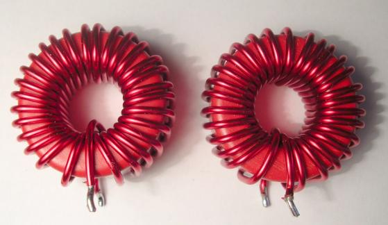
The toroids are T106-2, while bertus ones are T94.2, both with 1mm wire. Original AMP5 toroids are T80.2 with 0.7mm wire. All three coils are 11uH.
As now I have bertus coils on the table, I can post a picture:
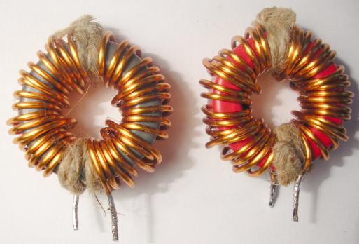
Time to test new coils now
Thomas
somebody said that bertus coils sound better because these have bigger toroid core and bigger wire than original coils coming with AMP5.
Having at home a pair of coils bigger than bertus ones, I decided to mount them on AMP5 to get better sound. Here they are:
The toroids are T106-2, while bertus ones are T94.2, both with 1mm wire. Original AMP5 toroids are T80.2 with 0.7mm wire. All three coils are 11uH.
As now I have bertus coils on the table, I can post a picture:
Time to test new coils now
Thomas
Hi,
Because measurements came up, and I'm also interested as an owner
of an AMP1, I thought I will give a try.
ya know, I'm that Network analyzer guy...
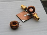
So I took out the coils of my recently defunt AMP3, and had measured
one intact, then disassembled, re-wind using the same piece of wire,
but with Bertus's method, that is, 5 steps forward, one back etc.
Here are the coils, one is on the test fixture:
Because measurements came up, and I'm also interested as an owner
of an AMP1, I thought I will give a try.
ya know, I'm that Network analyzer guy...
So I took out the coils of my recently defunt AMP3, and had measured
one intact, then disassembled, re-wind using the same piece of wire,
but with Bertus's method, that is, 5 steps forward, one back etc.
Here are the coils, one is on the test fixture:
Attachments
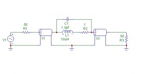
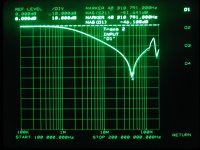
The test setup is like in the pic: the analyzer port1 sweeps the fixture from 100kHz to 200MHz, the coax line is interrupted in the fixture, and the coil is inserted. S21 is measured, that is, on port2 we are looking for the signal transmitted across the coil. As the coil's inductance rise with frequency, there will be an ever increasing attenuation on the output's 50 ohm termination. The parallel parasitic capacitance of the coil will form a resonant tank.
One pic is better than thousand words:
One pic is better than thousand words:
Attachments
Hi Thomas.
The BD15 are great. Two of them in parallel running at 103db sensivity. A stereo setup and you don't have to worry about the low-end any longer. Put them in a dipole enclosure, as Linkwitz or Ridtahler recommends. They will be running at 97db/W/m.
A perfect match to the Bastanis Dipoles. You'll get the woofer fully integrated.
Beside that they are 16Ohms. Connecting them in parallel, gives you a nice load for your amps.
I'll soon try a 2nd Charlize for the woofers to see if it fits better then the ice-powers. I am afraid that they are running a bit out of power.
By the way, why are you going for 11uH instead of 10uH?
Regarding your order:
Let Mundorf know, what you are using them for.
You can also refer to me <Klaus Schulz>
It'll take them a week to prepare.
Another issue - question to all:
Are the recommened 0,22uF filterCs in the output for 8Ohm loads
the way to go? Anybody out there who can give some advise?
Finally - I always have a good laugh about comments like ClassD4sure's.
BWRX said:................
If you were to use strands of Litz wire instead of a single wire, wouldn't it be more beneficial to have all the Litz strands laying side by side close to the core instead of having them all twisted together to form a psuedo wire that is then wound around the core?
I guess this would assume there is enough room on the core to place the litz wires side by side. A flatter conductor (like a long flat strip of insulated copper foil) that would hug the core might also be something interesting to try with a toroid core.
Yes that is perfectly feasible if you don’t have many turns. Actually I did that a lot for push-pull converter trannies wound on a toroide core and both primaries fitted in a single layer and were wound bifilair. But it requires good “hand winding” skills.
For a choke it does not have an advantage compared to twisted multi stranded wire. It is much, much more important to ovoid more than one layer to keep proximity effect lowest.
Yes, I know it, they are not beautiful, but they combine a number of improvements that I wanted to try all at once. When I found they really were an improvement, I was satisfied, but fortunately many people are not. No hard feelings if anyone finds another way to achieve the same or a better sound quality. And I really don't know which of the changes I made to the coils made a difference and which of them didn't.
Roger, thanks for your picture. I myself unfortunately don't have the time to draw pictures. What I did in my coil was to eliminate (or reduce) C5 and C9.
I'm looking forward to listening tests and measurements of other coil designs. Thomas' proposal for a test sounds great to me. Where you put the back-windings doesn't really matter as long as they are evenly distributed around the circumference.
Groet, Bert
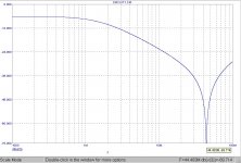
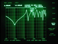
And here it is the measured curve:
The difference is the multiple reasonances with respect to reality. Though the first part coincides well.
The surprise for me was the not so great difference. Even, I would say it's a small difference only... The highlighted curve is the original coil,
the second curve is the "bank winded" one, a la Bertus.
The original resonance point was ~ 45 MHz, with the new coil it had shifted up to 48 MHz. In the sim I get the same shift while going from 1.3 pF to 1.1pF..
Attachments
Hi Bertus,
Apart from extra generated heat in general see it this way: Proximity effect causes extra frequency dependant losses (proximity effect is in fact an amplifying mechanism of skin effect in a certain way). If the pulse output of the chip is “perfect distortionless” the energy lost in the coil is subtracted from that perfect output causing distortion. Especially with the output of the Tripath chips where the frequency is largely signal level dependant.
So in a way the varying frequency causes frequency dependant losses causing distortion. So keep this losses as small as possible. One way is to avoid any magnetic material and use air cores and the other way is to avoid “wire” losses (which are still there with air cores). If you use iron powder keep peak induction as small as possible.
And to keep peak induction low locally in the core you will need to distribute the windings as evenly as possible around the circumference of the toroide. This holds more for cores with low mu_r like the distributed air gap iron powder cores than for cores with high mu_r
Pjotr,
So the larger diameter wire of Bertus means higher losses due to the skin effect - thinner wire would be better in this sense. Or Litz wire, to maintain low DC impedance. [But the question comes: why? Does it really matter the diff. between 0.001 or .007 ohms?]
Also the parasitic capacitance did not change too much - then what remains for explaining the [positive] differences?
Ciao, George
Testing inductors
All these tests and charts are nice but how does it relate to an 8 ohm load with a large signal? I don’t think it would be a simple scaling issue as there are a lot of nonlinearities to be considered. Even core heating can be a significant factor.
I would think that in spite of this the coil with the highest attenuation would be the one with the better performance. This should be true if the DC resistance is not more and if the core can handle the current without saturating.
As far as Litz wiring goes even 2 wires wound side by side will significantly reduce the parasitic capacitance and would be worth doing. More wires would be even better. Just be sure to keep the total cross sectional area the same so DC resistance doesn’t become more of a problem. This would only work with cores that don’t need many turns and these cores may have other issues like low saturation values.
The foil or tape wound coils are also interesting but I suspect would need to be quite large to get reasonable DC resistance and the needed value. There is also the issue of putting the inside turns to the source so the rest acts as a HF shield, this might be difficult to do. This is important as it will have a very significant effect on EMI.
I do like the idea of no core losses or hysteresis and no saturation limits but copper losses are or can be much greater due to there being so many more turns so this advantage disappears. Also as noted they are quite expensive in comparison. Still it could be worth it if they really are that much better.
You would think “but what about all that capacitance with the large surface area”? Yes the turn to turn capacitance would be quite high but you need to divide this effect by the number of turns so it becomes a non issue. There also is an extremely small amount of input to output capacitance in this configuration and this does help.
Roger
Roger,
This was what kicked me alive.. It is really that simple. There had been a lot of guesswork around, and also I got curious. If it can be measured, the changing resonance effects due to changing configurations, then why not have a look at it? And at least partially, you [all] were talking about parasitic capacitance. That scales fully to real life situation, that is, does not change an ounce if it's seeing 50 or 8 or 4 ohm load..
I would be a little afraid of foil or tape wound coils - that is the way axial capacitors are made..
Ciao, George
Why doesn't someone wind up a bunch and take some measurements
This was what kicked me alive.. It is really that simple. There had been a lot of guesswork around, and also I got curious. If it can be measured, the changing resonance effects due to changing configurations, then why not have a look at it? And at least partially, you [all] were talking about parasitic capacitance. That scales fully to real life situation, that is, does not change an ounce if it's seeing 50 or 8 or 4 ohm load..
I would be a little afraid of foil or tape wound coils - that is the way axial capacitors are made..
Ciao, George
So the larger diameter wire of Bertus means higher losses due to the skin effect - thinner wire would be better in this sense. Or Litz wire, to maintain low DC impedance. [But the question comes: why? Does it really matter the diff. between 0.001 or .007 ohms?
Hi George,
How much it counts? Only listening and/or distortion measurements will tell..
It is not important at audio signal frequencies, but for the HF ripple current flowing trough the coil. That causes mainly the losses which are modulated by the varying frequency. And at say 500 kHz the skin effect is huge with 1 mm round wire. Better look at varying energy that is lost in stead of varying impedances.
Note: We are talking about distortion figures some zeros after the point.
Btw did someone try these ones?
Pjotr,
Yes, I understand that thicker wire means much higher HF losses, and that means possibly more distortion.
What I didn't get, is the need for the thicker wire. Again, in the audio domain, does it mean anything that couple milliohms difference?
[Eventually the same audio current will go through that 1ohm 2mH input choke for the woofer..]
Ciao, George
Test results of coils with T106-2 evenly winded
Hi Joseph,
great job, but you forgot the twine. Out of joke, in bertus coils there are 2mm spacing halfways the toroids.
Maybe others will discuss technical issues, my contribution here is a listening session to add a piece to the puzzle.
Results:
The test was very easy: simply the new coils sound just as original AMP5 coils (T80-2 evenly winded 0.7mm wire). Perhaps worse, but now I'm used to bertus coils.
Highest and lowest range are compressed, while the rest is less detailed. These results are not nuances. The difference is big and in some listenings you can't hear thing you heard before.
The way I conducted the test is not objective (how could be?), but repeatable (as most reviews are not).
I played only three classical pieces very difficult to reproduce: the test consists in the fact that you can hear or not hear the things I'm going to tell:
1) Kodaly, sonata for cello solo n. 8 - 1. Allegro maestoso.
Look at resonances of cello case: you must be able to follow the shading of resonances completely. In lowest notes resonances can last one second or two. With bertus coils, resonances are complete, while with new coils are cutted soon.
2) Mahler, 4th Simphony - 3. Ruhevoll. In the middle violins play for a while in the highest octave: how many "fluxes" of sounds can you hear? With commercial amps this passage is unhearable, just like one a single violin at high volume in a built-in Windows player. With new coils I can hear just one single sound vaguely resembling violins; with bertus coils, violins similarly are seemingless, but you can hear two or three "fluxes" of sounds and even hear some vibration of bows over the strings. Live, you can clearly hear multiple "fluxes" to create the illusion of one single rich sound, while an expert conductor can distinguish the execution of each violinist.
3) Voices a cappella, doesn't matter what: only voices. Now count the voices, and count the voices following the same melody. With bertus coils the task is much easier.
Ciao
Thomas
Joseph K said:
what remains for explaining the [positive] differences?
Hi Joseph,
great job, but you forgot the twine
. Out of joke, in bertus coils there are 2mm spacing halfways the toroids.Maybe others will discuss technical issues, my contribution here is a listening session to add a piece to the puzzle.
Results:
The test was very easy: simply the new coils sound just as original AMP5 coils (T80-2 evenly winded 0.7mm wire). Perhaps worse, but now I'm used to bertus coils
.Highest and lowest range are compressed, while the rest is less detailed. These results are not nuances. The difference is big and in some listenings you can't hear thing you heard before.
The way I conducted the test is not objective (how could be?), but repeatable (as most reviews are not).
I played only three classical pieces very difficult to reproduce: the test consists in the fact that you can hear or not hear the things I'm going to tell:
1) Kodaly, sonata for cello solo n. 8 - 1. Allegro maestoso.
Look at resonances of cello case: you must be able to follow the shading of resonances completely. In lowest notes resonances can last one second or two. With bertus coils, resonances are complete, while with new coils are cutted soon.
2) Mahler, 4th Simphony - 3. Ruhevoll. In the middle violins play for a while in the highest octave: how many "fluxes" of sounds can you hear? With commercial amps this passage is unhearable, just like one a single violin at high volume in a built-in Windows player. With new coils I can hear just one single sound vaguely resembling violins; with bertus coils, violins similarly are seemingless, but you can hear two or three "fluxes" of sounds and even hear some vibration of bows over the strings. Live, you can clearly hear multiple "fluxes" to create the illusion of one single rich sound, while an expert conductor can distinguish the execution of each violinist.
3) Voices a cappella, doesn't matter what: only voices. Now count the voices, and count the voices following the same melody. With bertus coils the task is much easier.
Ciao
Thomas
- Status
- This old topic is closed. If you want to reopen this topic, contact a moderator using the "Report Post" button.
- Home
- Amplifiers
- Class D
- UcD180ad Vs 41Hz Audio AMP5 (Tripath TA2022)