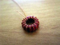
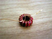
Ok, here's how to use the mobius winding technique.
Wind the wire the whole way around the core keeping the turns spaced apart by at least a wire width. Spacing will also depend on what final inductance value you're trying to achieve. Tighter spacing for higher inductance.
Wind the wire the whole way around the core keeping the turns spaced apart by at least a wire width. Spacing will also depend on what final inductance value you're trying to achieve. Tighter spacing for higher inductance.
Attachments
Hi soundcheck/Klaus and all others,
Thanks for the information on vibrations.
When winding my coils I have not tried to reduce vibrations, and the only way I can see I reduced them is by using heavier wire (mass and stiffness) and a heavier core (mass). By the way, I think toroid coils are less sensitive to electro-acoustic effects than linear coils.
Once and for all, my bank-winding practice, mentioned by Jan in his documentation with AMP1B and by Tripath in their documentation of the chip, is as follows: winding 6 lies on top of 4 and 5, winding 12 on top of 10 and 11, winding 17 on top of 15 and 16, winding 25 on top of 23 and 24, and winding 33 on top of 31 and 32. "On top of" means here: on the inside of the core on top of these windings, on the outside, where there is more room, between these windings.
Groet, Bert
Hi Bert,
what do you think about moebius banking technique? Is it worth trying?
I have 2 pair of T106-2 bare toroids left, these are used in 41hz AMP2 using Tripath TK2350 chip with 29 turns of 1mm wire to get 11uH.
As bigger toroids and ticker wire seem to get better sonic results i would try these on AMP5: one couple with evenly distributed windings, the other with your technique.
There would be no difference if it were only a matter of dimensions.
Is it correct to wind "on top of" the turns # 5, 10, 15, 20, 25?
Ciao
Thomas
Coil winding for reduced capacitance
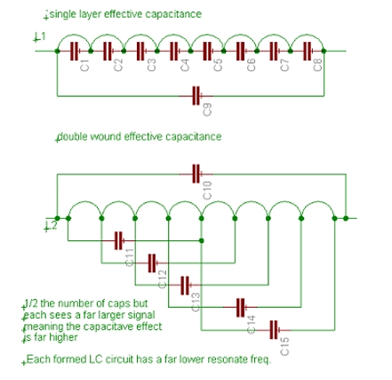
Sorry guys but I can't let this go. A single layer winding will be like having a very small cap between each winding. Since they all appear to be in series the actual overall value is very small. Now take the case where you space the windings out and put a second layer between the first round of wires. In this case the capacitance is connected from the input to ½ way down the core now multiply this times the number of turns and you will see probably several times increased effective capacitance. An impedance sweep vrs. frequency would show a much lower frequency point of the part going capacitive. Granted the number of effective capacitors has been cut in ½ but each sees way more signal voltage increasing its effect dramatically. Let’s say there were 20 turns total. This means each capacitor in a straight wound unit would see 1/20th of the signal now do the double wind trick and each cap sees ½ the total signal or 10 times more. So even though there are ½ the total number of effective caps they each are 10 times as effective. So the effective capacitance is 5 times as much in this example.
Roger
There was to be a picture here but I can't get it to post?????
Upseting as I spent some time on it!
Thank you for clearing that up Roger. You'll actually have the same number of parasitic caps with either method of winding and the amount of parasitic capacitance between adjacent windings will largely be the same as well (because the geometry between windings is basically the same if theyre evenly spaced). However, as you stated the parasitic capacitances of the mobius wound toroid will store a lot more energy due to the higher voltage across the parasitic capacitances (U = 0.5*C*V^2).
For a normally wound core with 8 turns, you'd have 8 total parasitic caps (7 adjacent windings and 1 start/end winding). The energy stored in the parasitic capacitance of each adjacent winding would be U = 0.5*C*(V/7)^2 = 0.01*C*V^2
Assuming the start/end windings are similarly spaced the stored energy in that parasitic capacitance would just be U = 0.5*C*V^2
For a mobius wound core with 8 turns, you'd still have 8 total parasitic caps (7 adjacent windings and 1 start/end winding) but the voltage differential between the adjacent windings is higher. The energy stored in the parasitic capacitance of each adjacent winding is a little more complicated. Three of the parasitic capacitances would would have U = 0.5*C*((3/7)V)^2 = 0.1*C*V^2, four of them would have U = 0.5*C*((4/7)V)^2 = 0.16*C*V^2, and the start/end winding would still have U = 0.5*C*V^2
From this you can easily see how more stored energy the same amount of capacitance will have with the mobius winding technique. Looks like I'll still be sticking with the normal winding technique!
Inductor winding stuff.
Brian,
Thanks for putting some numbers to it. I knew that my second drawing shows only ½ the caps but they are actually twice the value (active on both sides of the wires) so it works out the same.
There is also the fact that the formed resonate circuits will have a much lower frequency in the second example as the caps are larger and the enclosed inductance is far larger. This might be the most important part, defining at what frequency the inductor becomes capacitively reactive and starts lowering in impedance. This could be greatly different between the 2 examples and could potentially cause an EMI problem at the higher frequencies by giving the noise a clearer path out.
Roger
classd4sure said:Why doesn't someone wind up a bunch and take some measurements
Easier said than done.
What do you want to measure? Intercoil capacitance?
Inductance, saturation, THD, IMD, frequency range, DCR, Q?
And under what condtions? DC bias, current levels, switching frequencies, etc.?
Sorry to rain on the parade, but measuring inductors isn't as easy as it seems. Then we have to figure out what the results mean!

Hi,
What I am missing in this discussion is the value of the Q of the inductor. A lower Q means more losses! To raise Q and make it less dependant of frequency you'll need winding techniques that minimises proximity effect, that is minimizing direct magnetic inter winding coupling.
The mobius winding technique is one of them but what I remember from college is that this technique consist of placing one or two turns along the whole width of the coil and going back and forth the width of the coil each next turn: Like the way self supporting HF coils are wound, giving the coil a “braided” appearance. A step further to improve Q is the way honeycomb coils are wound. But I see no way to accomplish this on a toroide ferrite former.
Still the best way to wound optimum toriode coils is to use a large enough toroide to wound one single layer with evenly spaced turns along the full circumference and with some airspace between each turn. And to raise Q further you will need litze wire too.
I did wound power filter chokes with high ripple current on MPP cores. The difference in generated heat at 100 kHz between 25 x 0.2 mm litze and plain 1 mm round wire was dramatic.
Cheers
Thomas:
Here it is.
http://mundorf.com/english/bauteile/frspule.htm
It is a copper foil coil. The coil is wound around a wooden core.
On request, they are taking some windings off to get to 10uH.
They charge the price for the smallest size coil.
Don't ask for a silver coil quote. You'll fall of the chair.
Quote Mundorf.com:
In contrast to conventional coils, where the individual turns of the windings lie side by side, the windings in these units are directly on top of one another, bringing them significantly closer to the theoretically ideal coil. Among other things, this is reflected in the coils Q-factor, which remains constant up to more than 100KHz. And since the unwanted capacitance of these coils is particularly low they are also extremely effective at blocking out very high frequencies. Mechanical robustness is another valuable feature of this design. The large contact area between the windings and the elastic polypropylene film insulator eliminates vibration in the individual windings very effectively.
Quote End
By the way: I'd be happy to take the million for the Shakti Blind test! I just wanted to mention it. My intention was not to start up a discussion! By the way: I tied also one to each of my DDDAC1543-Towers with the same result: More focus, lower noise, less grain.
Bertus:
As you can see on Mundorf.com the thicker the wire the lower
the vibration impact. As you can also see there are dependencies on how the surface of the wire is treated. Which most probably
will have an impact on the capacitance.
By increasing the diameter of your wire you should have gained
lower vibration impact thats for sure.
If you want mechanically stable coils you’d better try vacuum epoxy impregnation
I usually cover the final coil with epoxy glue (UHU Hart performs pretty well) and then put it on the heating plate of my coffeemaker for a few hours. The heat makes the epoxy water thin for a while so it flows capillary between all gaps..
I usually cover the final coil with epoxy glue (UHU Hart performs pretty well) and then put it on the heating plate of my coffeemaker for a few hours. The heat makes the epoxy water thin for a while so it flows capillary between all gaps..
soundcheck said:
Hi soundcheck,
thanks for the information! I saw that page but I didn't know I could order custom coils. I'm going to order four 11uh copper foil coils.
Excuse me about Shakti stones. I didn't know anything about them, just suspected they were too nice to be true, so I searched Google and found the link I posted. Now Chris (classd4sure) will persecute you forever
.Congratulations for your system, I'm envious of your speakers.... how sound the Bert Doppenberg DB15?
Ciao
Thomas
eLarson said:
The handles for the 300.2 cost $80 by themselves. ::shudder:: I didn't happen to see a price on it on the link you posted, but I'm sure it's there somewhere.
(ARC created a class T? I really must be living in a cave!)
Same here! I shunned all news, newspapers, politics, television,etc.. for nearly 10 years. Now that I'm actively looking again, I am as disheartened of the broader human condition as I was before, and the pace of the insanity is even more out of control. Bloody lemmings.
I'll have to get a look inside one, if I can. Buy one, take it apart. Unless someone knows of a place for detailed photos of the innards???
KBK said:I'll have to get a look inside one, if I can. Buy one, take it apart. Unless someone knows of a place for detailed photos of the innards???
They have invented air cored coils too!

Look here: http://www.diyaudio.com/forums/showthread.php?postid=944709#post944709
- Status
- This old topic is closed. If you want to reopen this topic, contact a moderator using the "Report Post" button.
- Home
- Amplifiers
- Class D
- UcD180ad Vs 41Hz Audio AMP5 (Tripath TA2022)