BWRX said:
I would have to agree with Chris here... You want the windings as close to the core as possible, evenly distributed, and not overlapping (if possible). Plus, what in the world is that twine doing on there?
Hi Chris, Brian, Andrewbee,
sometimes poor solutions lead to great improvements... the twine is there to mantain a distance of 2mm between halfway windings (18-19 and 36-1). There are more elegant ways to do that, but, who cares?
The irregular distribution of turns, together with 5 turns lying on top of others, has to do with interwinding capacitance reduction.
Here is what explained diymember bertus, who built the coils and kindly sent them to my home:
Originally private post by bertus
I ordered some T94-2 cores from CWS and wound them with 1mm copper. I gave them 36 turns, for 11uH. Between first and last winding I kept 1 to 2 mm distance by putting in some binding string I had lying around, and halfway I did the same between windings #18 and #19. This way I aimed to reduce interwinding capacitance. Evenly distributed around the circumference are 5 turns lying on top of the others, in a bank-winding manner.
The differences between my coils and the original coils are:
- thicker wire, for lower resistance (better damping)
- thicker toroid core, therefore much less heat production
- higher saturation current
- smaller interwinding capacitance, so the highest frequencies (high
harmonic frequencies of the square wave) are shielded much better.
Which of these factors make the difference I do not know.
Indeed, predicted results on higher frequencies are there.
Ciao
Thomas
thomaseliot said:The irregular distribution of turns, together with 5 turns lying on top of others, has to do with interwinding capacitance reduction.
Spacing the turns farther apart does decrease interwinding capacitance but layering the turns increases interwinding capacitance.
Why do you need the twine to space the turns apart at the top of the inductor?
Pjotr said:Hi Thomas,
You made it with the UcD's
But to my experience bypassing the collectors of T2 and T3 with 100 uF / 63V Panasonic FC caps to Gnd works as good as a good external 12V supply.and is a lot less hassle.
Cheers
Hi,
Don't know about that. I can see it offering some improvement however the onboard regulators will still have rather poor "input" regulation as a function of the output.
Using the aux supply will provide independancy and I'd imagine that should improve the soundstage and imagery.
There are some cheap onboard ceramics nearest to the op amp rails in older versions which can seriously use some upgrading as well.
I'd be a little worried about lifting the pads wiring it like that though, maybe some audiophile auto silicon just for a little strain relief.
BWRX said:
Spacing the turns farther apart does decrease interwinding capacitance but layering the turns increases interwinding capacitance.
Why do you need the twine to space the turns apart at the top of the inductor?
I'm afraid I'm not the right guy to discuss these things. I only know the improvement is dramatic. I'm wondering too why these are so good.
Yes, layering the turns is a sort of bank winding technique for decrease the end-to-end capacitance.
Quote from a TI article:
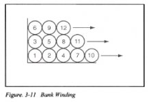
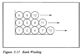
End-to-end capacitance, sometimes called "distributed capacitance", appears in shunt with a winding. In a transformer, this capacitance results in series and parallel resonances with mutual inductance and leakage inductances. In a filter inductor, the end-to-end capacitance, above resonance, passes the high frequency components of the switched waveform through to the output.
.....
With bank winding, the capacitance between physically adjacent turns has little effect because there are few electrically intervening turns, thus low voltage across the capacitance, compared with the conventional "back and forth" winding technique.
here is the link:
http://focus.ti.com/lit/ml/slup125/slup125.pdf
Bertus, where are you?
Ciao
Thomas
Attachments
Hi to everyone,
All of you making fun of my coils ? This must be because you didn't hear the sound they produce.
And .. I do agree, the coils are not very neat.
But, the improvement in sound quality they brought about was something I couldn't have expected.
The coils I designed are a combination of several improvements that I didn't test separately, and for my part I don't think it is worthwile to try to separate the effects of the different improvements.
I see that thomas elliot did already disclose some of the secrets, and I will try to give some extra information.
For my AMP1's and AMP1B's (identical to AMP5, but with SMD parts) I ordered some T94-2 cores from CWS and wound them with 1mm copper. I gave them 36 turns, for 11uH. Between first and last winding I kept 1 to 2 mm distance by putting in some binding string I had lying around, and halfway I did the same between windings #18 and #19. This way I try to reduce interwinding capacitance. Evenly distributed around the circumference are 5 turns lying on top of the others, in a bank-winding manner (bankwinding means that windings are not in contact with windings lying far upstream or downstream, but only with neighboring windings).
Coils of this size do fit on the AMP1 board snugly, and on the AMP1B board I had to tilt some electrolytes to widen the space a littlebit, but this was not very difficult. The 1mm wire is about the thickest that passes through the holes in the PCB, but this makes soldering somehow easier.
We (my daughters and me) tested the T94-2 with 1mm copper against the T68-2 with .6mm wire and against the T82-2 with .7mm, both combinations provided by Jan (Jan Fredriksson). Since the results were quite similar I will not describe both tests.
I mounted a T94-2 together with a smaller core in the two channels on one board and connected both inputs to the same signal, both the right side of a stereo signal from a cd-player. I plugged a simple two-way bassreflex loudspeaker alternately to one amplifier and the other. What I expected to find was an improved bass performance because of lower internal resistance of the amplifier resulting in a higher damping. This I found. At first my daughters disagreed, but when I asked them from which amplifier they heard a bass-string being played and from which they heard just a low note, they soon agreed. For the rest of the spectrum I found the same kind of improvement. The small core gives a 'rich' treble sound, the T94-2 gives a clear string, a clear voice, many strings playing together without loosing their individuality, many voices singing together without loosing themselves and above all the warmth created not by distortion but by presence and discernability. My daughters said 5 voices singing Ockegem a capella sounded from the small coil more like singing in a church, but when I asked them from which coil they heard 5 distinct, non interfering voices they again quickly changed their minds; I think children nowadays are used to bad sound quality and cold synthetic music. We agreed that all but some music is improved by the T94-2; when I tried my daughter's Nelly Furtado cd, it was displayed in all its deceiving artificiality. But this certainly does not apply to all pop-music. Hearing Ibrahim Ferrer singing I started thinking I understand Spanish (which I do not), so really clear and near he sounded.
I must conclude that the improvement brought about by using T94-2 cores for the AMP1 is dramatic, and to me completely unexpected. It moves AMP1 into another class!
When it comes to output filter cores Tripath says that smaller cores do not saturate, which is no doubt true, but on the other hand they do not say that the smaller cores behave in a linear way, and here the clue could be, although I do not quite understand; maybe non-linear behaviour produces audible combinations of supersonic frequencies, resulting in intermodulation distortion (?).
The differences between my coils and the original coils are:
- thicker wire, for lower resistance (better damping)
- thicker toroid core, therefore much less heat production
- higher saturation current of the coil
- more linear behaviour of the coils
- smaller interwinding capacitance (by bank winding and geometrically separating windings), therefor much better shielding of the highest frequencies (high harmonic frequencies of the square wave).
- probably a different brand of core material (there is a small difference in the colour coding of the core material)
Which of these factors make the difference I do not know.
Groet, Bertus
Try making some inductors with your T94-2 cores, ONE layer with a few more turns that are tighter to the core, and maybe a 5mm gap between the start and end.
The ones you have now probably sound better mainly because you are using a larger core (and a different material?) with thicker wire. Reducing interwinding capacitance and start to end gap capacitance is definitely good, but adding a second layer of 5 turns is not one way to reduce interwinding capacitance. Likewise, adding a gap at the top of the inductor will only reduce the capacitance between those neighboring windings and will increase the capacitance between the non-neighboring windings because they will now be closer together. Keeping them evenly spaced the whole way around the core is better.
The ones you have now probably sound better mainly because you are using a larger core (and a different material?) with thicker wire. Reducing interwinding capacitance and start to end gap capacitance is definitely good, but adding a second layer of 5 turns is not one way to reduce interwinding capacitance. Likewise, adding a gap at the top of the inductor will only reduce the capacitance between those neighboring windings and will increase the capacitance between the non-neighboring windings because they will now be closer together. Keeping them evenly spaced the whole way around the core is better.
Inductor winding
Brian is correct! Think of it this way, any ripple or switching signal across the inductor is divided equally between the turns therefore there is a greatly reduced signal between adjacent turns. This makes the capacitance between turns far less damaging. It is like a whole bunch of small caps in series so their effective value would be far less than the capacitance formed by overlapping the end windings. This end capacitance would see the full signal and the way it is wound effectively puts them in parallel, not a good thing. This means the inductors characteristic curve (Z/F) goes capacitive at a much lower frequency.
Roger
Good topic. I can certainly tell you that differnt core materials have different effects on the AF, as well as the RF. It doesn't seem to be so much an effect of saturation (within limits), as that of the core itself. Winding also seems to make a difference.
Unfortunately, my testing isn't advanced enough yet to really sort out the differences. Maybe soon. But the inductors really do influence the sound. Core type , wire size, winding techinique, they all play a role.
Unfortunately, my testing isn't advanced enough yet to really sort out the differences. Maybe soon. But the inductors really do influence the sound. Core type , wire size, winding techinique, they all play a role.
classd4sure said:Hi,
Don't know about that. I can see it offering some improvement however the onboard regulators will still have rather poor "input" regulation as a function of the output.
Using the aux supply will provide independancy and I'd imagine that should improve the soundstage and imagery.
There are some cheap onboard ceramics nearest to the op amp rails in older versions which can seriously use some upgrading as well.
I'd be a little worried about lifting the pads wiring it like that though, maybe some audiophile auto silicon just for a little strain relief.
Hi,
It’s all about power supply noise rejection. I did do it for the Ucd180_AD version. The AD8620 input opamp has already a huge PSRR at low frequencies. Only what needs to be improved is PSRR at higher frequencies and 2 simple extra caps will do. Here is a Pspice simulation of the PSRR:
Top trace is the bare on-board regulator and bottom trace is with extra 100 uF FC caps (ESR = 0.25 ohms) just after the voltage dropping resistors R60, R61 If you ad this up to the PSRR of the AD8620 itself which is ….
Sonic improvement (less noise, more “quiet sound”
) of the separate 12V PSU is not better than these extra on-board caps, at least to my ears.I glued the caps with a small drop of 2 component polyurethane glue (very strong stuff) on top of the transistors. Be careful with silicone glue, the regular ones contain acid (vinegar). Use a special acid-free one specially intended for gluing mirrors.
Cheers
interwinding capacitance
Brian,
Find out about bank-winding !
There is no extra layer of 5 windings in my coil. There are 5 evenly distributed extra windings, that only touch their direct neighbours; they nowhere get near windings further 'upstream' or 'downstream'.
Close-reading will do it !
Groet, Bert
Brian,
Find out about bank-winding !
There is no extra layer of 5 windings in my coil. There are 5 evenly distributed extra windings, that only touch their direct neighbours; they nowhere get near windings further 'upstream' or 'downstream'.
Close-reading will do it !
Groet, Bert
Hi folks.
I am running a T-2020 with copper-air-foil coils in the output.
I learned that vibrations on the inductor are causing servere
degradations on the output. And not only the earlier discussed interwinding capacitance. I guess the vibrations are causing even more degradations! Bertus improved the vibration behavier by seperating the windings. Perhaps that's another reason why it sounds better.
Have a look:
http://www.mundorf.com/deutsch/bauteile/frspule.htm
It is in german - however it shows clearly that coil-vibrations have a huge impact on the sound, depending of what kind of material and winding you apply.
To avoid the coils from catching RFI/EMI I covered the coils with ERS sheet!
10uH coil cost 10$ each. What a great invest!
By the way, try to glue a Shakti-Online Stone to the back of the Tripath ship and also cover it with ERS. This will lift the whole thing further up then applying the coil-tweak.
Cheers
\Klaus
IBM-T40
DDDAC1543-24-USB (heavily modded)
S&B TX102
Charlize (heavily modded)
Bastanis Kingtone (98db/fullrange dipoles)
Subwoofer:
DCX2496
Icepower1000ASP
Doppenberg BD15 (2*2 - Linkwitz Dipole config, 98db/w/m)
Battery-Supply with Northstar NSB90FT (<3mOhm), BG buffered
ALL electrolytics BG-N in Super E, Coupling Mundorf Silver/Gold
Re: interwinding capacitance
So did you wind X number of turns on the core back to the start position, then continue to wind 5 more evenly spaced turns and get back to the start position? I guess Im having a hard time understanding your "bank-winding" technique (which doesn't return much after searching on Google for a while).
I did however come up with a description of mobius winding technique where you wind the odd turns first (or just wind around the core once with space between the turns) then wind the even turns in between the odd turns when you come back around. That is something I haven't tried and would definitely be a good way to reduce interwinding capacitance.
bertus said:Brian,
Find out about bank-winding !
There is no extra layer of 5 windings in my coil. There are 5 evenly distributed extra windings, that only touch their direct neighbours; they nowhere get near windings further 'upstream' or 'downstream'.
Close-reading will do it !
Groet, Bert
So did you wind X number of turns on the core back to the start position, then continue to wind 5 more evenly spaced turns and get back to the start position? I guess Im having a hard time understanding your "bank-winding" technique (which doesn't return much after searching on Google for a while).
I did however come up with a description of mobius winding technique where you wind the odd turns first (or just wind around the core once with space between the turns) then wind the even turns in between the odd turns when you come back around. That is something I haven't tried and would definitely be a good way to reduce interwinding capacitance.
bank winding
repetita iuvant here a previous post
see:
http://focus.ti.com/lit/ml/slup125/slup125.pdf
BWRX said:
I guess Im having a hard time understanding your "bank-winding" technique (which doesn't return much after searching on Google for a while).
repetita iuvant
here a previous post
see:
http://focus.ti.com/lit/ml/slup125/slup125.pdf
soundcheck said:
I am running a T-2020 with copper-air-foil coils in the output.
.....
10uH coil cost 10$ each. What a great invest!
Hi SOUNDCHECK,
I couldn't find 10uh copper-air-foil coils at 10$. Can you please post a link? Or you mean air core inductors?
Thanks
soundcheck said:
By the way, try to glue a Shakti-Online Stone to the back of the Tripath ship and also cover it with ERS. This will lift the whole thing further up then applying the coil-tweak.
I'd be more prudent with Shakti stones. Look here.
If you are able to demonstrate a sound difference with Shakti stones in a blind test, James Randy has 1 million dollars ready for you!

Thomas
Ah, thank you for resposting that Thomas. It seems I missed your last post about this a page back.
To quote the article you linked to "In a multi-layer winding, end-to-end capacitance is reduced dramatically by sectionalizing the winding along the available length-a technique often used in
RF chokes, probably impractical in SMPS magnetics."
The key to that statement is multi-layer winding. The toroids you're using are only multi-layer in the sense that the second "layer" of 5 windings are sloppily placed between the windings of the first "layer". The whole twine at the top of the core to introduce a gap in the windings is pointless as well. You want the windings evenly distributed when using a powdered core. It even says so in that article on page 3-9:
" If the gap is distributed, as in a powdered metal toriod, then the winding should be uniformly distributed around the core."
If you really want to decrease interwinding capacitance try using the mobius winding technique I mentioned in my last post.
I still believe most of the improvement you're hearing with bertus' inductors is due to the larger core and the larger diameter wire.
Hi Brian,
I'm no sure to understand Moebius winding: are you going to try this technique with your amps? If so could you post a picture? I will build two and compare with bertus ones (i've not so much electronic knowledge, but good ears and recordings).
Chris,
what about copper foil inductors? I know from an old thread you were going to build a pair... have you news?
Audio Research use copper foil inductors for its Tripath based 150.2 amp. As inductors make so great sonic differences in Tripath chips, maybe it's worth trying.
What do you think?
Ciao
Thomas
Thanks Chris. I'm by no means an expert with this stuff but thought it made sense too.
Hi Thomas. The quality of the inductor used in the Tripath based amps makes a big difference because it is outside of the feedback loop.
I will try the mobius winding technique with my low power (10W) modules and see if I can get an improvement in the sound.
Conceptually, the technique is similar to the picture you posted. You wind the core the whole way around with the turns spaced apart the width of the wire you're using. Then you go around again, filling in the gaps. It will look like a single layer toroid when it's finished but will have reduced interwinding capacitance. I'll wind one right now and take some pictures.
This has got me thinking that a mobius wound, air core toroid would be the ultimate inductor to use in a class d output filter. This of course would not be economical in any way but is doable for one off diy projects
- Status
- This old topic is closed. If you want to reopen this topic, contact a moderator using the "Report Post" button.
- Home
- Amplifiers
- Class D
- UcD180ad Vs 41Hz Audio AMP5 (Tripath TA2022)