A tuned mass damper suppresses the resonance peak of an oscilating system at Fres by oscillation of the damper in the opposite direction, thereby distributing the energy concentrated in one large peak into two smaller peaks below and above Fres.
But again without friction this motion would go on forever. The damper makes the oscillation less violent, but it does not absorb energy, exactly because of the conservation of momentum that you mention.
To kill the oscillations, frictional elements are needed to convert movement energy into heat.
A crankshaft also has a tuned mass damper to suppress violent oscilations, but to kill the energy this damper is connected via a rubber ring to the crank acting at the same time as the frictional element.
So maybe in case of the 2CV these frictional elements are the tyres, but I would have expect some form of frictional damping in the shock absorber also.
Hans
Eddy currents dissipate heat without contact and lower the Q of a resonance just as viscous damping does. One needs a clearer definition of "friction" in this context. As frequency/velocity lowers to the simple motion of the stylus in the groove the damping vanishes below that of the residual friction due to the actual contact of a mechanical damper. There is also no stick/slip static vs dynamic friction issue either.To kill the oscillations, frictional elements are needed to convert movement energy into heat.
Hi Scott,Eddy currents dissipate heat without contact and lower the Q of a resonance just as viscous damping does. One needs a clearer definition of "friction" in this context. As frequency/velocity lowers to the simple motion of the stylus in the groove the damping vanishes below that of the residual friction due to the actual contact of a mechanical damper. There is also no stick/slip static vs dynamic friction issue either.
As always respecting your opinion, I reply with some hesitation, trying to avoid who is right or wrong. But the discussion itself is an interesting one.
Friction IMHO can be any process that converts motional energy into heat.
This can be internal friction, like in the elastomer suspension of the cantilever, the rubber mounting of a crankshaft damper, eddy current, etc.
But it can also be an interaction between two bodies, like dry friction, fluid friction or skin friction.
In case of internal friction, there is no residual friction.
But I can very well imagine a small vertical tube filled with some fluid with a metal ball in the middle, held in place by two spring.
A ball being a bit smaller as the tubes diameter, could move up and down with no stick, the fluid acting as the friction element dissipating the motional energy.
Fres of the Ball/spring combination should be around 10 Hz.
Taking a 4 mm ball weighting ca. 0.5 gram, two springs of 1 N/m would be needed to keep the ball in the middle.
Length of the tube (15mm?) and viscosity of the fluid still to be determined.
Idea worth trying ?
Hans
I like this idea. If I understand correctly, the goal is to achieve critical damping of the arm motion. Could it be done at the opposite end, at the counterweight?
I have seen on some arms the counterweight is attached by a rubber insert, could be for the same damping purpose.
I have seen on some arms the counterweight is attached by a rubber insert, could be for the same damping purpose.
I reply with some hesitation, trying to avoid who is right or wrong. But the discussion itself is an interesting one.
There's no right or wrong unless I'm confused. Both types of damping reduce the Q of a mechanical resonance the Q to the first order is determined by the loss which gets modeled as heat in a resistance. Viscous damping is complicated because there are components that can be proportional to velocity and velocity squared and there might even be turbulent flow. Springs can also have mechanical non-idealities. My only point was that with eddy current damping there are very few complications, I don't see any issues down to the current noise of the eddy current.
For damper we can use glass tube of amplifier fuse. For time being instead of spring a little piece of sponge ? OR if we are placing it vertical a same size plastic bead will help the steel ball float perhaps. If some how we can control viscosity we can tune it also.
Regards

Regards
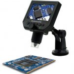
Latest thing for experimentation into centering records. £34 delivered from Hong Kong! I didn't expect much of it, but on a precursory check last night even with the stock stand you can examine the inner locked groove. Test tonight will be if I can successfully show eccentricity. Then the challenge will be adjusting it.
I've mislaid my nice steel ruler but sure I can find something to give me a measure of scale so I can get an idea of the accuracy I can readily get to.
It's not the lathe scope I really wanted, but got under the approvals limit")
I've mislaid my nice steel ruler but sure I can find something to give me a measure of scale so I can get an idea of the accuracy I can readily get to.
It's not the lathe scope I really wanted, but got under the approvals limit
Attachments
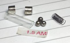
I put a small fuse in boiling water and with some effort managed to get the cap off. Also found supple spring and ball bearing. I dont have means and knowledge to measure things as I don't have PC at home. But will make micro damper soon.We all know from experience the metal caps on a glass or ceramic fuse will only come off when you don't want them to. If you want the metal caps to come off, then the glass will surely break.
Ray K
Regards
Attachments
You mean this?Has anyone here ever tried the old Discwasher "DiskTraker" pneumatic damper?
YouTube
looks like its working. on a smaller scale if we attach it to cartridge or on counterweight as said by lcsaszar would be great as it will not interfere with cartridge working as was the case with Shure brush.
Regards.
I run some tests for my proposal of magnetic damping device.
Please see the photo for construction of the device. I used 1 mm x5 mm x 8 mm magnet blocks to form a 6” long magnetic strip with double side foam tape and electrical tape. A 9 mm x 15 mm disc was installed on the air bearing above the magnetic strip.

I run tracks 7a, 7b, 8a and 8b from Cards Frequency Sweep test LP. Beside that, I run two pink noise files from a different test LP.
In order to see if the damping device works, I run tracks without the damping using Denon DL-103R cartridge with VTF 2.5 g. I ripped first file without any damping. The result was file damping00.wav. Then, I turned the magnetic disc down to close to the magnetic strip to increase the damping force. I measured VTF again. It increased to 3 g. I adjusted counter weight again to maintain VTF at 2.5 g. The result was file, damping05.wav. Repeated same procedure twice. I got files with 1.0 g damping force, damping10.wav and 1.5 g damping force, damping15.wav. I did same for pink noise, pink00( no damping) and pink15(1.5 g damping force).
Here are the test results.
Dropbox - damping00.wav
Dropbox - damping05.wav
Dropbox - damping10.wav
Dropbox - damping15.wav
https://www.dropbox.com/s/cyglfxaxt854ylp/pink00.wav?dl=0
https://www.dropbox.com/s/gius9bnore9vytg/pink15.wav?dl=0
All files contain four tracks and have 5 seconds interval between tracks.
The tracks are
1. 65.4 Hz, both channels, in phase(lateral modulation)
2. 65.4 Hz, both channels, out of phase(vertical modulation)
3. 49 Hz, both channels, in phase(lateral modulation)
4. 49 Hz, both channels, out of phase(vertical modulation)
two pink noise files with no damping and 1.5 g damping.
This damping device has no lateral damping. But I wouldn’t completely disregard lateral damping for my air bearing arm yet. I watched the arm when it moved on lateral tracks. In my opinion, it was probably better to have some lateral damping as well from observing the movements of bearing. The arm movement looked like the tail wags the dog. The needle didn’t move but the bearing moved from side to side.
Hans,
I would appreciate if you can do some analysis in depth.
Jim
Please see the photo for construction of the device. I used 1 mm x5 mm x 8 mm magnet blocks to form a 6” long magnetic strip with double side foam tape and electrical tape. A 9 mm x 15 mm disc was installed on the air bearing above the magnetic strip.
I run tracks 7a, 7b, 8a and 8b from Cards Frequency Sweep test LP. Beside that, I run two pink noise files from a different test LP.
In order to see if the damping device works, I run tracks without the damping using Denon DL-103R cartridge with VTF 2.5 g. I ripped first file without any damping. The result was file damping00.wav. Then, I turned the magnetic disc down to close to the magnetic strip to increase the damping force. I measured VTF again. It increased to 3 g. I adjusted counter weight again to maintain VTF at 2.5 g. The result was file, damping05.wav. Repeated same procedure twice. I got files with 1.0 g damping force, damping10.wav and 1.5 g damping force, damping15.wav. I did same for pink noise, pink00( no damping) and pink15(1.5 g damping force).
Here are the test results.
Dropbox - damping00.wav
Dropbox - damping05.wav
Dropbox - damping10.wav
Dropbox - damping15.wav
https://www.dropbox.com/s/cyglfxaxt854ylp/pink00.wav?dl=0
https://www.dropbox.com/s/gius9bnore9vytg/pink15.wav?dl=0
All files contain four tracks and have 5 seconds interval between tracks.
The tracks are
1. 65.4 Hz, both channels, in phase(lateral modulation)
2. 65.4 Hz, both channels, out of phase(vertical modulation)
3. 49 Hz, both channels, in phase(lateral modulation)
4. 49 Hz, both channels, out of phase(vertical modulation)
two pink noise files with no damping and 1.5 g damping.
This damping device has no lateral damping. But I wouldn’t completely disregard lateral damping for my air bearing arm yet. I watched the arm when it moved on lateral tracks. In my opinion, it was probably better to have some lateral damping as well from observing the movements of bearing. The arm movement looked like the tail wags the dog. The needle didn’t move but the bearing moved from side to side.
Hans,
I would appreciate if you can do some analysis in depth.
Jim
Last edited:
I put a small fuse in boiling water and with some effort managed to get the cap off. Also found supple spring and ball bearing. I dont have means and knowledge to measure things as I don't have PC at home. But will make micro damper soon.
Regards
Turned mass damper doesn't have to be complicated. A hanging mass can work too. A tuned mass damper is a system for damping the amplitude in one oscillator by coupling it to a second oscillator. If tuned properly the maximum amplitude of the first oscillator in response to a periodic driver will be lowered and much of the vibration will be ’transferred’ to the second oscillator. The joint of hanging mass can be a micro ball bearing. The turned mass damper will be more effective if it hangs lower. For a pivot arm, it can be hung on the back part of arm and lower than the platter if only lateral damping is desired.
Thanks Super. I did assembled the damper. I have a record track (regional language) on which headshell can be seen vibrating; with equal tracking weight (with and without damper) I attached it with rubber band. Visually I can not see any movement. The spring is very soft like typical antiskate spring usually found on turntables. So either I need more ball bearing weight or softer spring.
No alternative than tuning the mass and taking measurements as you have said super.
Regards.
No alternative than tuning the mass and taking measurements as you have said super.
Regards.
Attachments
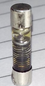
Nicely executed.Thanks Super. I did assembled the damper. I have a record track (regional language) on which headshell can be seen vibrating; with equal tracking weight (with and without damper) I attached it with rubber band. Visually I can not see any movement. The spring is very soft like typical antiskate spring usually found on turntables. So either I need more ball bearing weight or softer spring.
No alternative than tuning the mass and taking measurements as you have said super.
Regards.
In posting #964 I calculated two springs of 1N/m with a metal ball of 0.5 gr.
In case of using just one spring, a 2 N/m spring should be used.
2N/m means approx 200gr/m or 0.2gr/mm.
A 0.5 gram ball should shorten the spring in that case by 2.5mm.
This is a very weak spring and looking at your spring I suspect yours to be much stronger, resulting in a Fres that is much too high and therefore being ineffective for the purpose.
I'm, still thinking how to construct this spring.
Hans
I run some tests for my proposal of magnetic damping device.
In order to see if the damping device works, I run tracks without the damping using Denon DL-103R cartridge with VTF 2.5 g. I ripped first file without any damping. The result was file damping00.wav. Then, I turned the magnetic disc down to close to the magnetic strip to increase the damping force. I measured VTF again. It increased to 3 g. I adjusted counter weight again to maintain VTF at 2.5 g. The result was file, damping05.wav. Repeated same procedure twice. I got files with 1.0 g damping force, damping10.wav and 1.5 g damping force, damping15.wav. I did same for pink noise, pink00( no damping) and pink15(1.5 g damping force).
Here are the test results.
Dropbox - damping00.wav
Dropbox - damping05.wav
Dropbox - damping10.wav
Dropbox - damping15.wav
Dropbox - pink00.wav
https://www.dropbox.com/s/gius9bnore9vytg/pink15.wav?dl=0
All files contain four tracks and have 5 seconds interval between tracks.
The tracks are
1. 65.4 Hz, both channels, in phase(lateral modulation)
2. 65.4 Hz, both channels, out of phase(vertical modulation)
3. 49 Hz, both channels, in phase(lateral modulation)
4. 49 Hz, both channels, out of phase(vertical modulation)
two pink noise files with no damping and 1.5 g damping.
This damping device has no lateral damping. But I wouldn’t completely disregard lateral damping for my air bearing arm yet. I watched the arm when it moved on lateral tracks. In my opinion, it was probably better to have some lateral damping as well from observing the movements of bearing. The arm movement looked like the tail wags the dog. The needle didn’t move but the bearing moved from side to side.
Jim
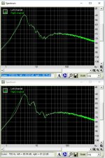
Being in a bit of a hurry, I did a quick check on the noise recordings.
The upper one is pink00, the lower one pink15.
The conclusion is up to you
Hans
Attachments
- Status
- This old topic is closed. If you want to reopen this topic, contact a moderator using the "Report Post" button.
- Home
- Source & Line
- Analogue Source
- Turntable speed stabilty