Thanks Hans!
From pink noise, I can tell nothing. It seems to me that it is not good signal to do this kind of test. I see the arm/cart resonance is at 4 Hz. It matches what I did before. However, the vertical and lateral resonances are mixed. I see dips around 20 Hz. It has more to do with arm/cart performance.
Jim
Thanks Hans!
From pink noise, I can tell nothing. It seems to me that it is not good signal to do this kind of test. I see the arm/cart resonance is at 4 Hz. It matches what I did before. However, the vertical and lateral resonances are mixed. I see dips around 20 Hz. It has more to do with arm/cart performance.
Jim
Just take a recording of a silent track. Most resonance will be vertical.
<snip>Nicely executed.
In posting #964 I calculated two springs of 1N/m with a metal ball of 0.5 gr.
Weak is an understatement. I looked at what specialist spring suppliers can do and 4N/m is the best I have found so far. We are looking for something like a single strand of the elastic from that ancient underwear that won't stay up any more! I suspect that a fishing weight clamped onto thin elastic might be close.This is a very weak spring and looking at your spring I suspect yours to be much stronger, resulting in a Fres that is much too high and therefore being ineffective for the purpose.
I'm, still thinking how to construct this spring.
Of course what would be nicer is full 360 degree damping rather than a single plane, which I'm still trying to visualise. Some sort of torsion bar into a damping trough.
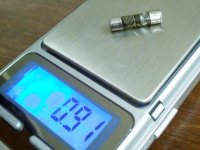
Hans, thanks for the numbers. The whole thing weighs 0.91 gms. The steel ball weighs 0.12 gms. I put in two. Obviously it did not work*
Bill, I wonder if we need spring at all. I observed while handling this feeble contraption, without spring, filled with sewing machine oil and held vertically the single ball settled at the bottom very very very slowly. If placed vertically and ball kept in the middle by a string will probably also work. OR discard the oil put on a appropriate springy flexible wire with weight attached at the end (Like angler fish) may also work. A 360 degree damper.
* Pardon me for not being clear. I was trying to see visible (As I don't have measuring tools as of now) damping of vibration of that particular track mentioned earlier which vibrated the whole headshell and not the resonance which is main aim of the damper.
Regards.
Attachments
Last edited:
Bill,Of course what would be nicer is full 360 degree damping rather than a single plane, which I'm still trying to visualise. Some sort of torsion bar into a damping trough.
A body of proper shape, hanging in a trough filled with a viscous fluid, and connected at some distance to your head shell, would give you the 360 degree damping.
However, I don't like the idea having a trough hanging above my LP's.
Sooner or later you will have oil drips all over the place.
There is also the question whether you really need a 360 degree damping.
There is no music content below 20 Hz , and noise below this frequency seems to be out of phase, or vertically modulated ??
Hans
Discwasher DiscTraker links
????????????????????? ( ????? ) - subrosa???? - Yahoo!???
DiscTraker???? ( ????? ) - subrosa???? - Yahoo!???
????????????????????? ( ????? ) - subrosa???? - Yahoo!???
DiscTraker???? ( ????? ) - subrosa???? - Yahoo!???
Hans: can understand your issue with silicone fluid near the moving end. From that perspective the SME FDIV solution is nice as it damps at the bearing*. Perhaps orthogonal mass dampers would do what is needed. Certainly lots to experiment with.
* I think we can assume tonearm is rigid at 10Hz?
* I think we can assume tonearm is rigid at 10Hz?
I have tried to put everything in a model to get a better feeling for quantities.
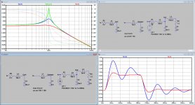
In the images below, you see 3 circuit diagrams.
The most left one is representing the Cart, having a compliance of 15um/mN (C4).
The weight of the cartridge is 12.1 grm, but to get the Fres of my Cart/Arm system, the effective mass including the arm must be ca. 16 grm (L4).
To get a resonance peak of 10 dB, the polymer suspension will have to present an internal friction of 0.3N (R2).
These parameters put in the model, are shown in the FR with the Blue line.
The FR of a 0.5grm ball (L1) on a 2N/m spring, or a compliance of 0.5m/N (C1) as proposed, having the same Fres as Arm/Cart, is shown in Green.
The combined FR of Cart/Arm with Damper is shown in Red.
To get the wanted damping, a Friction of 1.3N (R4) is needed.
The right side of the image shows the step responses of resp. the Cart/Arm without damper in Blue and the combination of Arm/Cart with damper in Red.
Hans
Attachments
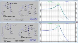
Never too old to learn, I was unhappy with the above results and started further searching.
Two things happened to be wrong:
1) The damping element in the Cart is integrated in the polymer Spring construction and should be parallel to the spring instead of in series.
2) I wrongly interchanged spring and mass for coils and capacitors..
For my MC cartridge this had no effect because compliance and effective weight happen to be the same, but for the attached damper it had a massive effect.
So I redid the simulations again assuming a Resonance Peak of 10dB, see Image below.
When using a 0.5grm ball with a 2N/m spring, damping at Fres will be 2dB when using the right damping fluid.
Going to a ball weighting 2.5grm with a 9.1N/m spring, damping will be 4dB with a more viscous fluid.
The first conclusion is that the heavier the ball, the stronger the spring and the more viscous the fluid, the more the damping can be achieved to suppress the resonance.
The drawback is that this extra weight is attached to your Cart/Arm, thereby effectively lowering Fres, setting a limit to how heavy the ball may be.
The second conclusion is that with a trough, filled with the correct damping fluid, a really critical damped system can be achieved, with hardly any weight added.
So more effective and much lighter and far easier to tune.
I also repeated the sim for a 6dB Fres Cart/Arm peak instead of 10dB.
Again using the 2.5grm ball, etc, the damping in this case was only 2dB.
So I must conclude that only with extremely accurate tuning, damping can be achieved, but the amount of damping is restricted..
It was a nice excercise, but for the above reasons, this option should be considered very carefully .
Hans
Attachments
Still thinking along the above lines, instead of connecting a tube filled with fluid, containing a ball and a spring to the headshell, one could also look at the other end of the arm.
When replacing the counterweight with one that is isolated from the Arm through some silicone or elastomer, this substance supposed to be acting at the same time as spring and as a damper, two important advantages are gained:
1) the effective mass of the arm does not increase when this new weight is just as heavy als the original one keeping the original Fres intact.
2) Damping works in all 360 degrees directions.
I will start some initiative in this direction, keep you posted.
Hans
Interesting. This is what I was thinking, and what Dual, Mission and I am sure some others did decoupled counterweights. Not sure how many measurements were done of efficacy and the 774 was known for counterweight sag over time.
I was not aware of these XTC products, maybe worth considering.
My idea was to have a concentric construction that works equally in all directions.
Yes but I looked around on other forums (VE, AK) and there are mixed results. Some say that the counterweight + rubber insert form a separate vibrating system, not necessarily tuned to the same frequency as the arm/pickup system, and there is a chance it is tuned in the audible range, because we have little control over it.
Now I have a Mayware unipivot arm, that has a small container filled with silicone at the pivot for damping purpose.
Also found this info:
Turntable Basics - Silicone Damping Fluid For Tonearm Cueing Mechanisms, Damping Troughs and Monopivots
Now I have a Mayware unipivot arm, that has a small container filled with silicone at the pivot for damping purpose.
Also found this info:
Turntable Basics - Silicone Damping Fluid For Tonearm Cueing Mechanisms, Damping Troughs and Monopivots
Last edited:
Quite right.Yes but I looked around on other forums (VE, AK) and there are mixed results. Some say that the counterweight + rubber insert form a separate vibrating system, not necessarily tuned to the same frequency as the arm/pickup system, and there is a chance it is tuned in the audible range, because we have little control over it.
What I noticed with all the simulations is the high sensitivity the relevant parameters.
There are two: Fres and the height of the res peak that should both be carefully taken into the equation to get a proper tuning.
A bit off and the result will be disappointing.
So there is absolutely no single solution that fits all situations, not even close, whereas a through can do the job in a much more universal way by selecting the right damping fluid.
Hans
Interesting read. Especially, mass, resonance and inertia.
Transcriptors Vestigal tonearm | Stereophile.com
Transcriptors Vestigal tonearm | Stereophile.com
Interesting read. Especially, mass, resonance and inertia.
Transcriptors Vestigal tonearm | Stereophile.com
Very amusing article, even more so to read the manufacturers reply.
Well written by Mr Gordon Holt, 44 years ago !
Last edited:
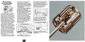
The decoupling of the counterweight on Dual arms was not a simple rubber collar.
Also, the elastomer parts were not exposed, so protected from UV. I have services 4-5 of old Duals, the behavior at the subsonic range was very good.
The ST line of B&O tonearms had the horizontal gimbal axis attached to a conical soft rubbery insert (damping at the vertical plane). It was exposed to the light. It degraded with time.
There was also a rubber bushing at the mounting of the arm to the armboard.
George
Attachments
- Status
- This old topic is closed. If you want to reopen this topic, contact a moderator using the "Report Post" button.
- Home
- Source & Line
- Analogue Source
- Turntable speed stabilty