My 2p worth as to mains-frequency type variation is that, by definition, it changes slowly and therefore isn't normally perceivable by most people - only a tiny few could resolve absolute pitch to within about 1/5 of a semitone (about 1% of frequency).
What is far more audible is relatively sudden change in pitch of a tone, such as warble or vibrato. The FM range as to threshold of audibility for step changes of a tone works out about 5 musical cents, or about +/- 0.15% of frequency, and some people even finer AFAIK. Particularly warble in the range 0.5Hz-30Hz, and especially if it modulates a natural or familiar sound.
So, IMO, focus on motor speed absolute accuracy is a distraction, though it's harmless. Short term variations by way of wow and vibrato matter far more to audibility, and in most cases where it occurs very simple mechanical faults dominate IME. In normal and otherwise healthy TTs, once per revolution variation and cart-arm stability dominate causes, even though mains frequency variation might numerically far exceed it in principle: we're not wired up to hear it......
LD
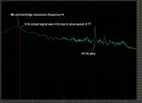
Well said. I can’t agree more. In the meantimes, I think the speed of driving system is fundamental part of LP playing back. Inaccurate speed may shift the frequency which excites arm/cartridge resonance. Here is a video to demonstrate that. My TT was running a little slow so the frequency shifted. From the video you can see the arm was excited at 5 Hz. In fact, it is not 5 Hz but about 4 Hz. My arm resonance is about 4 Hz.
arm/cartridge resonance lateral 17 Hz - 5 Hz band 2 - YouTube
I recently tried to put a 3150 Hz sweep into time/frequency waterfall to see if I can use waterfall to judge stability of TT speed. However, its resolution is far lower than LD’s software. I used Arta measurement software. It is a free try out software.
Thanks Jim, that's very interesting.
Can't quite see the scale on the spectrum chart, but the animation appears to show several broad spectrum elevations in noise floor as the test is swept.
I agree, one might suppose this is associated with an increase in random movement of the stylus due to momentary mistracking, after short term variation of effective VTF as the headshell moves. Effectively an increase in random crackle-pop noise at low VTF or due to altered stylus-groove friction as VTA and azimuth changes.
As to why there is apparently a series, I don't know. Could you post the exact frequencies at which it happens please ?
Thanks again, LD
Hi LD,
Here is a screen capture. The track I used was band 2 from side two of HiFi News Analogue Test LP. It is a Cartridge/arm lateral resonance test sweep 25-5 Hz(L+R)+ 1K Hz pilot tone. You can see from the screen capture that both my arm/cartridge resonance frequency, about 4 Hz and 5 Hz from test track are overlapping each other. It caused mis-tracking. A series of peaks by the 1K Hz are 2nd order harmonic frequency and 3rd order harmonic frequency, etc.
Jim
Attachments
I can only confirm this.
One day I removed the platter from the spindle on the two DDs I have here and I turned on their motors.
The spindle of the JVC QL-A2 was turning smoothly without any visible indication of cogging.
The spindle of Kenwood KD-3100 was cogging vigorously, there was no such thing as smooth rotation.
With the platters on (platters are light, almost identical), both TTs behave well.
George
That clever chap Arthur of pink triangle/funk devised a test to determine whether stylus drag had any effect on speed stability.
He built a deck with two arms. On the platter he placed a 12" test record cut with a 3150hz tone. On top of this he placed a 33rpm 7" record. A clamp held both records tightly to the platter. One arm played the test record fed to a wow and flutter meter whilst the other arm tracked the music cut into the 7". Any speed variation due to stylus drag whilst playing real music would be then easily seen on the meter.
Absolutely no speed variation was seen. Stylus drag is NOT a contributing factor in speed stability.
Having read through this thread the one product that continues to spring to mind, and has been mentioned several times, is the Townsend damping trough. I have had the pleasure of living with a Townsend rock reference in the past and can attest to the effectiveness of this simple bit of kit.
Hi Jim,
It occurs to me from the analysis done by LD that the mass of your peripheral clamp might be overloading your main bearing and this is the cause of the greater speed variation. Hopefully you have not caused any damage to your bearing. A clamp of only about a quarter the mass of your current design should still be capable of flattening warps just as efficiently but would not load the bearing as much. The use of greater mass for its flywheel effect does not appear to be beneficial in this case.
Niffy
Hi Niffy,
When I made the outer ring, I wanted to add mass to the platter as well. It seems to me that the ring is little too heavy for the motor. I don’t know if the outer ring has damaged the bearing. In short term, it should be ok, but I can’t tell for long term. I am thinking of modifying the bearing for a while and want to use a roller air bearing. Please see the video for roller air bearing I am talking about. However, I am not sure if I can do it yet. Roller air bearing is expensive. 20 mm ID roller bearing is about USD$800. I don’t know if I can get some parts done at a reasonable cost. If I can modify the SME table’s bearing, I may want to add even more mass on the platter.
Here is the roller bearing video.
OAV ® Roller Air Bearing - YouTube
Jim
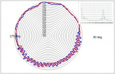
Cogging doesn't show up to any great extent in a healthy TT of good pedigree because it typically isn't there IME. One can generally see it in the FM spectrum inset, but almost always swamped by other effects as we have discussed here.I was wondering if most motors more or less cog why it doesn't show in polar plots ?
Doesn't matter what drive type, one is hard pressed to tell from just trying to find effects of drive cogging in the polar plot: it's barely there (typically) and swamped by other infuences on pitch stability.
All drive types are capable of providing stable platter rotation, IME, and would be splitting hairs to say one general type is better than another - at least for a good healthy example.
Here's an example of drive cogging in a faulty idler wheel TT (Lenco IIRC), it shows up nicely since it only affects part of the platter revolution. It's still possible that this TT was considered 'normal', because the extent of the fault isn't that great, but should still be audible I think.
LD
LD
Attachments
I dont know if this is right thread but would any kind soul answer this. It is said that weight at cartridge is good at damping vibrations/resonance (at the source) so...
1) Why are headshells usually very light, filmsy or most of the mass is removed from them by cutting circles ?
2) What is the natural resonant frequency of vinyl record material ?
Thanks in advance.
1) Why are headshells usually very light, filmsy or most of the mass is removed from them by cutting circles ?
2) What is the natural resonant frequency of vinyl record material ?
Thanks in advance.
I dont know if this is right thread but would any kind soul answer this. It is said that weight at cartridge is good at damping vibrations/resonance (at the source) so...
1) Why are headshells usually very light, filmsy or most of the mass is removed from them by cutting circles ?
2) What is the natural resonant frequency of vinyl record material ?
Thanks in advance.
Hi Hiten,
I have not heard this one. Adding mass at the headshell will not damp vibrations/resonance. It will lower the frequency at which the arm/cantilever system resonates but the peek of this resonance will tend to be of a greater magnitude.
Headshells tend to be lightweight in order to keep the overall effective mass of the arm low enough to put the compliance resonant frequency at around 10hz. It is better to have more of the arms material towards the centre/yoke as this is where the greatest bending moments will occur and less at headshell where the minimum bending moments are.
Vinyl doesn't have a set resonant frequency. The resonant frequency of an object is determined by the properties of the material it is made of (Young's modulus, density, Poisson's ratio, shear modulus, damping coefficient etc.) It's mass and its shape/mass distribution. Also a record does not exist in isolation. It is normally coupled to a platter and mat. The record-mat-platter make a system that resonates as a single entity not as three disparate systems each with its own resonant frequency.
Niffy
Niffy. It saddens me the low prices that townsend TT's sell for. I am looking at ways of making damping troughs without needing machining capabilities. So far 10x16mm conduit is looking promising")
The main problems with using conduit are that the channel needs to be curved for use with pivoted arms and that of sealing of the ends. Silicone fluid has a habit of creeping through even the slightest gap. A watertight trough might still leak silicone and the last thing you want is to get any on a record. I would recommend manufacture from a solid block if possible. This can be done with a router from a slab of acrylic or such like. Alternatively, a 3D printer could make an exact clone of the original Townsend damping trough. Or you could try and get an original as a spare part though this goes against the spirit of diy. Jim (super) has more experience with damping trough design than I so he may be able to advise.
Niffy
PVC plus hot air gun=curved conduit. That bit is easy.
Will admit the sealing of the ends will need thinking about.
Bill
Try Methyl Ethyl Ketone (MEK) while you hand-press the bulkheads against the ends of the channel (assuming good contact and no voids at mating surface)
George
- Status
- This old topic is closed. If you want to reopen this topic, contact a moderator using the "Report Post" button.
- Home
- Source & Line
- Analogue Source
- Turntable speed stabilty